
Use Manual


6
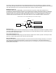
detects the FM IF signal. One input of the quadrature detector is connected internally to the IF signal from pin 11 while
the other input is the phase-shifted signal from Y102 at Pin 10. Demodulated audio appears at Pin 9, where a lowpass
filter formed around U303-C removes the spurious second IF output prior to application to the voice, tone and squelch
conditioning audio circuitry.
Two types of squelch circuits exist, an RSSI squelch and a NOISE squelch. Both types can be used
simultaneously or either one or the other can be used. The RSSI (receive signal strength indicator) squelch, which is
typically set around –108 dBm, must be set to open at a higher level than the noise squelch. This is necessary since the
RSSI measures total power in the receiver IF bandpass. All background noise, which at VHF can be high, is seen as
signal. The advantage of the RSSI squelch is that it opens and closes the audio paths very quickly. The noise squelch
has the advantage that it can be set at a much lower level, typically –121 dBm for 12 dB SINAD. It takes longer to open
and close noise squelch. If both are used simultaneously, since they are ORed together at U301 pin 32, the squelch will
open quickly and close slowly for strong signals. The RITRON programmer can be used to adjust levels or turn one or
the other off. A dual colored LED will shine green when carrier is detected.
Voice and Tone Conditioning in Receiver
Three post demodulation paths are provided. U303c provides DC level translation to bias succeeding op amp
stages at about 1.6 volts. The audio then gets de-emphasized by R366 and C364. The audio path then goes through a
fourth order 300 Hz highpass filter U308b and U308c. The 1 watt audio amp is turned on by Q304 and Q301.
The audio and data signals go through a programmable adjustable gain inverting buffer stage U303d, used to set
the output voltage.
Sub-audible signals go through a third order 250 Hz lowpass filter U303b. Pin 27 of U301 decodes the CTCSS or
DCS signal. In the case of CTCSS the processor, using an internal discrete Fourier transform, looks for the wanted
tone. Decode bandwidth is about +/-2 Hz.
Receiver Current Consumption
The radio will monitor the channel until a carrier becomes present. When an on channel carrier appears, the
carrier detect line (pin 13) will be pulled high through a 390 ohm resistor R309. If the correct CTCSS or DCS tone is
present the radio will unsquelch the speaker and auxiliary output lines. In standby mode the radio consumes 25 mA or
less. When unsquelched the audio PA is turned on. If only the auxiliary output and no voice is needed current
consumption can be reduced by disabling the audio PA. This is done by removing R383 and will bring current
consumption down to about 35 mA during receive. If a modem is used that is able to monitor the auxiliary output
continually then AUX_MON can be tied low. By disabling both RSSI and noise squelch, (both levels set high) the
current can be reduced to 25 mA.
TRANSMITTER
Voice and Tone in Transmitter
In transmit mode two audio paths and one tone path exists. The microphone input is a high gain pre-emphasized
path. U308-D along with C359, C360, R363 and R374 form a 300 Hz high pass filter. This filters out audio voice
components that will disturb DQC decoding. R364 and C362 form the pre-emphasis network. Signal limiting occurs in
U303-A. “Splattered” higher frequency components are later filtered out by the fifth order 2500 Hz low pass filter
consisting of U304-C and D. Microphone gain can be adjusted with the AUX_IN gain e-pot.
The AUX_IN, with a flat frequency response, goes through an inverting adjustable amp U303-A. The AUX_IN gain
should be adjusted so that with the desired signal level the required deviation is transmitted. With high level inputs
deviation limiting occurs in U303-A. The unit is preset in the factory to limit at +/- 5 kHz with high input levels and give
+/- 3 kHz (+/- 1.5kHz narrowband channel) deviation with 300 mV peak-to-peak input. Either the microphone input or
the AUX_IN input should be driven at any one time. The two paths combine in the U303-A limiter.
The CTCSS and DCS sub-audible tone are generated by the U301 pin 13. These tones are generated by the pulse
width modulated (PWM) output at pin 13 of the microcontroller. The 8 bit PWM output operates at 28.8 kHz. A third
order low pass filter consisting of R346, C332 and U304-B suppress harmonics higher than 300 Hz for QC and DQC
tones.
Both the VCO and the reference oscillator are modulated by all signals resulting in a nearly flat frequency
response from DC to 2500 Hz. The FM deviation of the VCO is set by the “deviation” potentiometer U307-C. The
reference oscillator’s deviation and VCO balance is adjusted by the “balance” pot U307-B. The balance pot is adjusted
to give a minimal tilt on an 800Hz generated waveform. The CTCSS deviation from 67 to 254 Hz lies between 600 and
900 Hz in wideband mode.