
Use Manual


8
MICROCONTROLLER
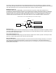
The DTX-145M transceiver is electronically controlled by U301, an 8-bit flash programmable microcontroller. U301
has A/D inputs and PWM outputs for processing analog signals. Radio characteristics are stored in internal EE
memory. Its RS232 port is used in programming the radio’s personal characteristics such as frequencies and tones.
PIN DESCRIPTION
1 Input is pulled LOW when the PTT input is grounded to initiate transmitter operation.
2 Input is pulled low when high/low power input is grounded. This produces a low RF output power.
3 GROUND
4 +3.3 VDC V
CC
supply voltage.
5 GROUND
6 +3.3 VDC V
CC
supply voltage
7 OSC1 is 14.4 MHz reference input from Y301.
8 Output goes high when audio PA is enabled.
9 Output SCL4 data line for controlling frequency and power e-pot.
10 Output drops low momentarily to produce synthesizer latch enable (LE) pulses.
11 Output goes low to enable receiver (/RXEN).
12 Output SCL3 data line for controlling AUX_IN and AUX_OUT gain e-pot.
13 TONE OUT generates the QC (CTCSS) or DQC (DCS) waveforms via an 8 bit PWM in transmit mode.
14 Output SCL2 data line for controlling DEVIATION and BALANCE e-pot.
15 DATA output sends serial data to frequency synthesizer U401 to program frequency information. Also used for
flash programming (MOSI)
16 CLK output sends serial data clock pulses to frequency synthesizer. Also used in flash programming (MISO).
17 Connects to pin 6 of J401. Grounding this defeats synthesizer unlock reloading for diagnosis.
Also outputs SCL1 data line for controlling NOISE and RSSI squelch e-pot.
18 AVCC gets +3.3 VDC for A/D convertors.
19 Input used to measure receiver RSSI.
20 AREF supplies the reference level for the A/D and is connected to the regulated +3.3 VDC.
21 AGND supplies A/D ground.
22 Input is normally low when PLL is locked.
23 Input is pulled low when the CS2 frequency bit input is tied to ground.
24 Input is pulled low when CS0 channel select bit is pulled low.
25 Output goes low to enable transmitter (/TXEN).
26 Input is pulled low when CS1 channel select bit is pulled low.
27 CTCSS IN is an A/D input decoding the CTCSS or DCS waveform.
28 Input is pulled low when radio is commanded to MONITOR channel.
29 RESET is held low to start the radio in a known state on power up.
30, 31 SERIAL DATA PORT links the microcontroller to communications from an external data terminal via
programming port pin 9 of J301. This allows programming of the DTX-145M EE memory used to store channel
frequency and configuration information.
32 CARDET gets pulled low when a RF carrier is detected.