
Use Manual


9
DTX-145M ALIGNMENT PROCEDURE
Only an authorized RF service technician should perform test and alignment of the DTX-145M. The unit is PC adjusted.
RECOMMENDED TEST EQUIPMENT
1) 12.5 to 14 VDC 2 Amp current-limited power supply 3) Oscilloscope
2) RF Communications Test with: 4) Sine wave generator around 500 Hz
- FM Deviation Meter
- RF Wattmeter 5) RITRON PC Programming Kit
- Frequency Counter
- SINAD Measuring Device
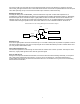
RADIO PREPARATION
2) Connect the FM communications test set to the antenna connector.
3) Connect RITRON programming cable to radio and PC.
4) Apply 12.5 to 14 VDC to the red wire with the black to ground.
5) Run RITRON DTX software and read the radio.
RADIO ADJUSTMENT
The DTX-145M is preset at the factory for 2 watts at 12.5 VDC. The programming software includes help
comments. If DTX needs to be changed or readjusted do the following:
1) Make sure that the unit is at room temperature and voltage between pin 6 and pin 15 is at least 12.5 VDC while
transmitting. There may be significant resistive losses causing voltage drop in the supply cable.
2) Set the RF communications test set to the transmit mode. Make sure equipment is calibrated including coax cable
and adapters. Note that a 1 dB cable loss will yield a 20% power loss.
3) Make sure the Hi/low power pin 5 is unconnected. This selects high power.
4) Run RITRON DTX LS programming software.
5) On the menu bar select Edit then Tune radio.
6) If starting from scratch, set up the radio in the order the buttons appear from top to bottom on the left: Frequency,
Mod Balance, Deviation, Power then User Set Up. Otherwise, adjust what is needed.
7) Click Frequency then Tune.
8) The frequency used in adjustment is displayed in the upper right corner.
9) Radio will transmit in center of band. TX frequency is displayed in upper right hand corner of form. Adjust frequency
by clicking arrows or by click in space to right of sliding button (for up) or space left (for down). Button can also be
dragged to position.
10) Adjusted transmitter frequency reading should be less than +/-100 Hz. Click Save when done.
11) Adjust positive and negative corrections in the same way. This calibrates the reference oscillator.
12) If the reference oscillator ages and drifts in the future, only the center frequency should need trimming.
13) Apply a 500 Hz sine wave at sufficient level to AUX_IN input (pin 7). We want the sine wave to limit and appear as
a square wave when demodulated by the service monitor.
14) Click Mod Bal then Tune and adjust for flat top on square wave. Repeat for balance high frequency.
15) Click Deviation then Tune and adjust for +/- 5 kHz. Repeat for deviation high frequency.*
16) Click Power. Notice that low and high power can be set globally or on specific channels. The factory preset is
global with high power set at 2 watts. The lower and upper power may vary a bit. Variable cap C207 (seen in the
hole in the PA shield) can be used to balance low to high frequency power. Also, channel specific low and high
power settings can be programmed on channels 1 through 8.
17) Make your choice of what you want to adjust and adjust it. Keep in mind when you adjust low or high power in the
“all channels” section you write that same setting in all channels.
18) Click User Set Up. Here, you can adjust NOISE and RSSI squelch levels and AUX_IN and AUX_OUT gain. If both
RSSI and NOISE squelch are used simultaneously, the RSSI level must be set first with the NOISE squelch
disabled. Disable it by adjusting the level so high (bar to the right) that the RF level never reaches it. The NOISE
and RSSI squelch levels work as an OR function. With either level exceeded, the audio will turn on. Set the RSSI
level around -106 dBm and then the NOISE level around -120 dBm.** When adjusting AUX_IN level apply your
desired signal level to pin 7. The unit was factory preset with a 300 mVpp sine wave adjusted for +/- 3 kHz
deviation. This same level will produce +/- 1.5 kHz on a narrowband channel.