
User's Manual


OUTPOST Wireless Callbox Basic Operation
Have questions? Call 800-USA-1-USA (800-872-1872) or visit our website at www.ritron.com
5
OUTPOST INSTALLATION INSTRUCTIONS
The OUTPOST can be mounted to virtually any
surface with four (4) #6 panhead screws. Choose a
type of screw thread and screw length which will hold
firmly in the surface to which the unit will be mounted.
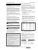
To MOUNT the OUTPOST: (Refer to FIG-1)
1. Loosen the (4) captive screws in the front corners
of the case and separate the case front from the
case back. These screws are captive to the
housing; to prevent damaging them, DO NOT
re-
move the screws from the housing.
2. Install 6 D-cell alkaline batteries into the battery
holder. Refer to FIG-1, or the labels beneath the
cells, for correct installation of the batteries.
3. If required, program the radio. Refer to the pro-
gramming section of this manual for details.
4. Disconnect the RF mating connectors and the
battery mating connectors. Set the case front
containing the radio circuit board aside.
5. Insert a #6 panhead screw into each of the four
(4) corner holes in the OUTPOST case back. Po-
sition the case back in the chosen installation lo-
cation and secure it in place with the four screws.
CAUTION
Do not drill or penetrate the OUTPOST case
with any additional holes. Use only the pre-
drilled mounting holes.
6. Re-connect the RF mating connectors and the
battery mating connectors between the case front
and case back.
7. Fasten the case front to the case back with the
four( 4) captive screws. Do not over-tighten the
plastic screws to prevent damage.
8. Insert, rotate and lock the antenna onto the an-
tenna connector. Orient the antenna vertically.
9. If the OUTPOST is to be used outdoors, it is im-
perative that the antenna connector be sealed
with sealing tape after the antenna has been in-
stalled. Use Grainger #2A-459, Radio Shack
#278-1647, or equivalent. Refer to “Sealing the
Antenna” instructions in this manual.
10. To install the message placard, align the center of
the hole over the ON/PTT Button, and the mush-
room-head fastener strips on the back of the
placard with the strips on the front of the Outpost
case. Press firmly to interlock the strips, snap-
ping the panel into position.
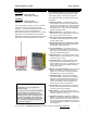
Coverage
Depending on the unit location and installation,
the OUTPOST can cover up to 1 mile. To in-
crease range, use an external antenna that is
mounted higher. See the RAM-1545 Magnet
Mounted Antenna on page ii.
XT OUTPOST INSTALLATION INSTRUCTIONS
The XT OUTPOST can be mounted to virtually any
surface with four (4) ¼” diameter fastners. Choose a
type of screw thread and screw length which will hold
firmly in the surface to which the unit will be mounted.
To MOUNT the XT OUTPOST: ( Refer to FIG-3)
1. Remove the front faceplate from the XT Callbox.
The faceplate is secured to the case with 4 van-
dal-resistant buttonhead, Torx screws. Use the T-
25 Torx bit included with the radio to remove
these screws.
2. Remove the “Mounting Bracket” kit secured to the
inside of the XT Callbox case.
3. Loosen the (4) captive screws in the front corners
of the internal Callbox case and separate the
case front from the case back. These screws are
captive to the housing; to prevent damaging them,
DO NOT
remove the screws from the housing.
4. Install 6 D-cell alkaline batteries into the battery
holder. Refer to FIG-2, or the labels beneath the
cells, for correct installation of the batteries.
5. If required, program the radio. Refer to the pro-
gramming section of this manual for details.
6. Fasten the internal case front to the case back
with the four( 4) captive screws. Do not over-
tighten the plastic screws to prevent damage.
7. Re-fasten the front faceplate to the radio with the
4 buttonhead Torx screws.
8. Install the 4 mounting brackets to the back of the
XT Callbox case as shown in FIG-3 below with
the #10-32 bolts provided. The mounting brack-
ets can be installed vertically, as shown, or hori-
zontally.
9. Position the XT Callbox in the chosen installation
location and secure it in place with four screws
through the mounting brackets.
FIG-2: XT Callbox Mounting Brackets
– Verticall
y
Installed