
User's Manual
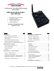


RBS-SERIES DMR/ANALOG BASE RADIO USER MANUAL RADIO OPERATION - GENERAL
Have questions? Call 800-USA-1-USA (800-872-1872) or visit our website at www.ritron.com 4
R
ADIO
C
ONTROLS AND
C
ONNECTORS
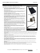
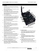
1 ANTENNA
The flexible antenna radiates and receives radio signals.
The antenna connects to a BNC type connector located on
the top end of the radio.
NOTE: The AFB-1545 antenna included with the radio will
work with VHF and UHF radios.
2 VOLUME DOWN / OFF BUTTON
Press the Volume Down / Off button to decrease volume.
The channel display will indicate the volume level as long
as the Volume Down / Off button is pressed. To turn Off
the unit, press and hold this button until the speaker
sounds a double beep.
3 ON / VOLUME UP BUTTON
To turn the unit On, press the On / Volume Up button; the
speaker will sound the Channel Beep. If the radio turns on
to the Scan Channel it will sound the Scan Beep. Once the
radio is On, press this button to increase volume. The
channel display will indicate the volume level as long as
the On / Volume Up button is pressed.
4 PUSH-TO-TALK (PTT) BUTTON
Press and hold the PTT when transmitting; release it to
receive.
5 AUDIO ACCESSORY JACK
The audio accessory jack is used to plug in earphone
options and, in conjunction with the microphone jack, to
connect an optional remote speaker / microphone or a
single-ear or dual-ear headset.
6 MICROPHONE JACK
The microphone jack is used to connect optional external
microphones and, in conjunction with the audio accessory
jack, to connect an optional remote speaker / microphone,
or a single-ear or dual-ear headset.
7 USB PROGRAMMING JACK
USB Mini B jack used for radio programming.
8 CHANNEL SELECTOR BUTTON
Press the Channel Selector button and the radio will
advance the channel. The Channel Beep will be heard any
time Channel 1 is selected. When the Scan Channel is
selected the radio will sound the Scan Beep and begin
scanning.
9 P1 BUTTON - PROGRAMMABLE SOFT KEY
The P1 Button is used for selective signaling. Use the P1
button to step through DMR or Analog contacts for
selective calling or control signaling.
10 P2 BUTTON - PROGRAMMABLE SOFT KEY
The P2 Button is capable of performing a variety of
functions. Function options: Channel Scan, Weather
Channel, Monitor, Send 2-Tone Code, Send Call Tone,
Send DTMF or Selcall ANI.
11 CHANNEL DISPLAY
The 2-line x 8-character channel display will indicate the
current operating channel when in standby. The display
will also indicate current operating conditions such as
volume, caller ID, DMR/Analog channel type, busy
channel, etc.
12 MICROPHONE
The microphone allows your voice to be heard in
transmissions to other radios. Speak in a normal tone;
shouting does not improve your listeners’ reception.
13 SPEAKER
The speaker allows you to hear calls on your channel.
14 POWER CONNECTOR (TOP END OF CASE)
The power connector on the top end of the radio is used to
connect power to the unit, either an external 12 VDC
supply or the RPS-1B cube power supply included with the
radio.
1
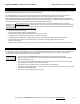
FIG-1: RADIO CONTROLS & CONNECTORS
5
6
7
8
9
4
3
2
10
11
12
13
14