
Owner`s manual


For assistance, call RITRON at 800-USA-1-USA (800-872-1872) or visit us at www.ritron.com
qtm9322b.pm5
7
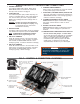
FIG
-
7: CONTROL & CONNECTION LOCATIONS
2 Standard
Modular
Telephone Jack
O
WNER
-
SUPPLIED
S
TANDARD
D
ESK
T
ELEPHONE
S
ET
,
SWITCHED
TO
P
ULSE
D
IALING
M
ODE
OWNER-SUPPLIED M ODULAR
TELEPHONE C ORD:
DO NOT CONNECT TO
TELEPHONE
LINE, BUT TO A
TELEPHONE
SET ONLY.
TO Q UICK A SSIST
TELEPHONE
JACK,
(ITEM 2).
4 Switch #1
Terminals
5 Switch #2
Terminals
3 Battery
Holder
7 Customer Service
Push-button
Connection
10 Compressed/Not-Compressed
Audio Select Jumper
6 External Power
Input Terminals
1 Antenna Co-Axial
to BNC Connector
9 Battery Type Selector
8 Transmitter Bandwidth
Select Jumper
IDENTIFICATION OF CONTROLS AND CONNECTIONS
1 ANTENNA CONNECTOR
The antenna radiates radio signals. Before using
Quick Assist, make sure the antenna is fastened
securely to this connector. See page 8.
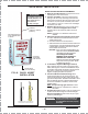
2 TELEPHONE JACK
The modular telephone jack provides temporary con-
nection to a standard pulse or rotary mode telephone
unit, which is used by the owner to program Quick
Assist voice messages and other settings. Refer to
FIG-7 below.
WARNING: DO NOT connect the Quick Assist to a
line from the telephone company; doing
so will damage the unit, and void the
manufacturer's warranty.
3 BATTERY HOLDER
The battery holder accommodates the six (6) standard
"AA" alkaline cells required to power the Quick Assist.
NOTE: ALWAYS INSTALL A FRESH SET of alkaline
batteries before programming the unit.
4 SWITCH #1 TERMINALS
Switch #1 terminals connect to the unit's front panel
(customer) push-button. When the button is pressed
and released, the Quick Assist transmits a voice
message (typically, a Customer Assistance message).
5 SWITCH #2 TERMINALS
Switch #2 terminals connect to the reset switch on the
bottom of the unit. When this reset button is pressed
and released, the Quick Assist transmits a voice
message (typically, a Reset message).
6 EXTERNAL POWER TERMINALS
Refer to page 6 for information to connect an external
12 VDC power supply to these terminals.
7 FRONT PANEL (CUSTOMER SERVICE) PUSH-BUTTON
When this push-button is pressed and released, the
Quick Assist transmits a voice message (typically, a
Customer Assistance message).
8 TRANSMITTER BANDWIDTH SELECT JUMPER
DO NOT remove this jumper. As described on page 5,
this jumper controls selection of wide or narrow
bandwidth.
9 BATTERY TYPE SELECT JUMPER
DO NOT remove this jumper. As described on page 5
this jumper controls charging the optional Ni-Cd
batteries.
10. COMPRESSED/NOT-COMPRESSED AUDIO SELECTOR
Do not remove this jumper.
The Quick Assist
can be used with two-way radios that use "companded
audio." For radios with Companded Audio -place the
jumper in the COMP position. For radios without
Companded Audio - place the jumper in the NON-
COMP position. To determine if your radio uses
companded audio, call Ritron or your radio supplier.
IMPORTANT:
Do not remove
any other fasteners or further
disassemble the Quick Assist unit; doing so risks
damage to the unit and voiding the manufacturer's
warranty.