R i t t a l GmbH & Co. KG Auf dem Stützelberg D–35745 Herborn Deutschland Germany Email: Info@rittal.de http://www.rittal.com Service -Tel. : (+49) - (0)2772 / 505 - 0 Service - Fax : (+49) - (0)2772 / 505 - 2319 Rittal PMC12 UPS-Manual 7857.430 7857.431 7857.432 1phase double conversion true online UPS System 1 - 3kVA FRIDHELM L O H GROUP A 38333 03 IT 74e.
Important Safety Instruction EN Microsoft Windows is a registered trademark of Microsoft Corporation. Acrobat Reader is a registered trademark of Adobe Systems Incorporated.
Important Safety Instruction Table of Contents 1. IMPORTANT SAFETY INSTRUCTION .............................................. 4 1.1. 1.2. 1.3. 1.4. 1.5. 2. 2.1. 2.2. DOCUMENTATION NOTES ........................... 4 RETENTION OF THE DOCUMENTS ................ 4 USED SYMBOLS ......................................... 4 AN IMPORTANT NOTICE .............................. 4 STORAGE INSTRUCTION ............................. 5 PRODUCT INTRODUCTION.... 6 GENERAL CHARACTERISTICS ......................
Important Safety Instruction 1. Important Safety Instruction 1.1. Documentation Notes The audience for this guide is the technical specialists familiar with the assembly, installation and operation of the PMC12 UPS-System. You should read this operating guide prior to the commissioning and store the guide so it is readily accessible for subsequent use. Rittal cannot accept any liability for damage and operational malfunctions that result from the nonobservance of this guide. 1.2.
Important Safety Instruction 15. Observe the valid regulations for the electrical installation for the country in which the unit is installed and operated, and the national regulations for accident prevention. Also observe any companyinternal regulations (work, operating and safety regulations). 16. Use only genuine or recommended parts and accessories (see Chapter 4). The use of other parts can void the liability for any resulting consequences. EN 1.5.
Product Introduction battery drain and helps extend the battery life span. 2. Product Introduction 2.1. General Characteristics True online technology continuously supplies your critical device with a stable, regulated, transient-free pure sine wave AC Power. 1. High-efficiency PWM sine-wave topology yields an excellent overall performance. The high crest factor of the inverter handles all high in-rush current loads without the need to upgrade the power rating. 2.
UPS Functional Descriptions 3. UPS Functional Descriptions 3.1. UPS Front Panel Display 3.1.1.
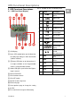
UPS Functional Descriptions 3.2. Rear Panel Descriptions EN 230V 1KVA 2KVA 3KVA 1. 2. 3. USB Port RS232 Port Emergency Power Off (EPO) Dry Contact Signal inputs 4. Communication Card Options Slot 5. External Battery Connector 6. AC power connection socket 7. AC Outlets 8. Two programmable outlets 9. Utility Input fuse holder 10. Cooling Fans 11. Output fuse holders 12.
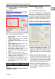
UPS Functional Descriptions 3.3. Operating Modes & Voltage System Configurations Download from www.rimatrix5.com/dl_power.htm the “Setting Tool” and open the Software to see the screen as below: **Sensitivity Low : 184~260V, High: 194~260V EN 3.3.2. Programmable Outlet Setting The UPS is equipped with 2 programmable outlets for use to supply to less critical loads.
UPS Functional Descriptions 4. Outlet Turn Off When Battery Lower than - select this option to automatically disable the outlet at the specified remaining battery power capacity(%) during battery mode to shed the less critical loads to prolong battery back-up time for the other more critical loads connected to the UPS. 5. Outlet Turn Off When Overload – select this option to automatically disable the outlet during overload condition (bypass mode) to possibly allow the more critical loads: • 3.4.1.
Installation and Operation 4. Installation and Operation EN Warning! Read the Safety Instruction guide (page 5 to 6) before installing the UPS! 4.1. Unpacking Inspect the UPS upon receipt. The manufacturer designed robust packaging for your product. However, accidents and damage may occur during shipment. Notify the forwarder and dealer if there is damage. The packaging is recyclable; save it for reuse or dispose of it properly. • • Remove the UPS from the carton box. Check the package contents.
Installation and Operation 4.3.2. Power Module + Battery Module Step 2 EN Step 1 Step 3 Step 2 Step 4 4.3.3.
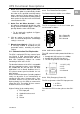
Installation and Operation 4.4. Operation EN 4.4.1. Start Up In Normal Mode 1. Make sure the voltage of Utility matches with the input voltage window of the UPS. 2. Connect the UPS to the wall Receptacle of the Utility. Turn on the UPS “ON” switch to start up the UPS. LED (Nr. 2) and (Nr. 5) light up to indicate the Utility and the Bypass are normal. The LCD will illustrate from drawing A to drawing B. drawing D drawing E drawing A 6.
Installation and Operation EN drawing L drawing H drawing M drawing I 4.4.3. Check Measured Values & Figures detected by UPS If you would like to check the measured values & messages, please use scroll up and scroll down key pads.
Installation and Operation EN drawing P2 2. Press key pad to scroll down the LCD screen, then check the UPS settings. The LCD display will show in sequence: drawing P1(buzzer) drawing Q1(self test) drawing R1(Bypass Voltage) drawing S(Output Frequency Synchronized Window) drawing T (Inverter Output Voltage) drawing U1(UPS Operation Mode) drawing V(Output Voltage Fine Tuning).
Installation and Operation 3. Press scroll up key pad, you may execute special functions. The functions include Buzzer ON (as drawing Q1) or buzzer OFF (as drawing Q2, Alarm silence for UPS warning) and self-test OFF (as drawing R2). UPS will execute battery test for 10 seconds, if the self-test is successful, it show as drawing W; otherwise, it will show as drawing D & error message at the same time. vated only when the UPS is re-turned on.
Installation and Operation (d) Turn off the Breaker of the Utility Input. (e) The UPS lock problem is solved now. 4.6. Battery Replacement EN Step 1 4.4.7. Shut Off 1. Press key pad for about 5 seconds, the Inverter output will be turned off, then the output load is supplied by Bypass loop and the LCD screen shows as Drawing B. 2. Turn off the input of the UPS. 3. The UPS is turned off completely. 4.5.
UPS Working Principle The table below provide a summery guide to the UPS operating modes against the Utility AC Power Source conditions. Step 4 1KVA Utility Conditions 2K/3KVA 5. UPS Working Principle 5.1. UPS System Block Diagram UPS Operating Modes Rectifier convert AC to DC, battery charging, Inverter convert DC to Mains Available AC and supply to loads with clean & stable power. Rectifier and charger stop operating, Battery discharge via DC~DC boost circuit and supply Mains Absent to Inverter.
UPS Working Principle 5.3. When Mains is Absent The working principle of the UPS under Mains absent condition is illustrated as follows: Fig 5.3 by the inrush produce by the loads, the UPS is equipped with electronics overload protection feature as standard. If the UPS loading is >105~120% of its capacity, it will switch to bypass mode in 30 seconds to protect the Inverter. If overload condition is eliminated by reducing the load to <105%, the UPS will switch back to Inverter mode automatically.
Maintenance Guide 5.5.2. Inverter/Internal Over temperature 6. Maintenance Guide If the UPS experiences internal over-temperature when Utility is normal, it will switch to bypass loop. The UPS will switch back to inverter mode when the over-temperature situation is eliminated. If over temperature occurs when Utility is abnormal, the buzzer will beep continuously and the Fault LED will light up. The UPS will cut off supply to the loads. 6.1. Trouble Shooting 5.5.3.
Maintenance Guide 6.2. Situation Check Items UPS fails to provide battery backup or its back up time is shorter than its intended performance. Solution If the backup time remains non-satisfactory after 8 hours of charging, please contact your local dealer for battery replacement. UPS is normal but Check if all power If problem no Output to load codes are properly persist, consult connected. your local dealer for technical assistance. The UPS switches 1.
Bundle Software Installation Guide 7. Bundle Guide 7.1. Software Installation consistent for the whole parallel system - or specific values from the single modules. UPS External SNMP-Adapter Hardware Installation 1. Connect the male connector of RS232/USB cable to the UPS communication port. 2. Connect the female connector of the RS232/USB cable to a dedicated RS232 port of the Computer. 3. For optional interface cards, please refer to Chapter 8 for more details. 9 Ethernet Internal SNMP-Card 8.1.
Customer Service erating Systems, analogous to PMC-Software. Our SNMP Interfaces are compatible to RCCMD. EN 9. Customer Service If you have any technical questions or questions concerning our product spectrum, contact the following service address: Tel.: +49 (0)2772/505-1855 http://www.rimatrix5.com E-mail: info@rittal.
Technical Informations 10.
Technical Informations Model Battery System 1KVA 2KVA 3KVA 12V/7,2Ah 12V/7,2Ah 12V/9Ah 3 6 6 Backup Time(20%) >66min. >66min. >59min. Backup Time(40%) >27min. >28min. >19min. Backup Time(60%) >14min. >14min. >12min. Backup Time(80%) >10min. >10min. >8min. Backup Time(100%) >7min. >7min. >5min. Type Numbers of Batteries Recharging Time Charging Current (Max.
Technical Informations Model 1KVA Short Circuit Battery EN 3KVA ABDM EPO Over Temperature 2KVA (Bypass Mode) <105% continuous >106% ~ 120% for 250 seconds shuts down >121% ~ 130% for 125 seconds shuts down >131% ~ 135% for 50 seconds shuts down >136% ~ 145% for 20 seconds shuts down >146% ~ 148% for 5 seconds shuts down >149% ~ 157% for 2 seconds shuts down >158% ~ 176% for 1 seconds shuts down >177% ~ 187% for 0,32 seconds shuts down >188% for 0,16 seconds shuts down Buzzer continuously alarms.
Technical Informations Model 1KVA Backup Time with Extended Battery Module 2KVA 3KVA >30min. EN Load 1 extended Battery module 2 extended Battery module UPS-Manual 100% >66min. >34min. 80% >90min. >52min. >46min. 60% >120min. >69min. >60min. 40% >180min. >109min. >95min. 20% >350min. >210min. >180min. Load 100% 80% 60% 40% 20% >130min. >160min. >220min. >325min. >630min. >66min. >90min. >160min. >180min. >350min. >60min. >75min. >109min. >160min. >310min.
Technical Informations EN UPS-Manual 28