
Operating instructions
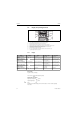
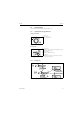

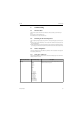

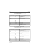

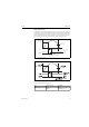
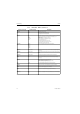
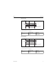
Table Of Contents
- Doku_Standard_Wasser-RK_GB_V09.pdf
- General description
- Important safety measures
- Transport and handling
- Installation
- Electrical connection
- Start-up
- Hydrological data
- Maintenance
- Shutting down / disposing the cooling system
- General fault analysis
- Evaporator pressure
- Compressor is continuously being switched on and off
- No medium circulation
- Appendix
- Datenblatt_060535.pdf
- PID.pdf
- Schaltplan_englisch.pdf
- MPRA-SMK-A-0-Englisch.pdf
- BA_PMA-KS40-1_41-1_42-1_englisch.pdf
- Contents
- 1 Mounting 5
- 2 Electrical connections 6
- 3 Operation 10
- 4 Configuration level 21
- 4.1 Configuration survey 21
- 4.2 Configuration 22
- 4.3 Set-point processing 29
- 4.4 Configuration examples 30
- 4.4.1 On-Off controller / Signaller (inverse) 30
- 4.4.2 2-point controller (inverse) 31
- 4.4.3 3-point controller (relay & relay) 32
- 4.4.4 3-point stepping controller (relay & relay) 33
- 4.4.5 Continuous controller (inverse) 34
- 4.4.6 D - Y - Off controller / 2-point controller with pre-contact 35
- 4.4.7 KS4x-1 with measured value output 36
- 5 Parameter setting level 37
- 6 Calibration level 41
- 7 Programmer 44
- 8 Timer 46
- 9 BlueControl 49
- 10 Versions 50
- 11 Technical data 51
- 12 Safety hints 55
- Index
- Contents
- Parameterliste PMA_english.pdf
- BA_Strömungswächter_SI1000_englisch.pdf
- BA-IFM_Drucksensor PN7009_englisch.pdf
- Endress-Hauser-Display BA188Ra3_englisch.pdf
- Endress-Hauser-Messsonde_BA_englisch.pdf
- BA_FEC12_englisch.pdf

Commissioning RIA452
68 Endress+Hauser
6.3.4 Digital input - DIGITAL INP./M5
The settings for the digital status inputs, e.g. for monitoring pumps, starting/stopping the counter
or resetting the min/max-value memory are grouped in this section.
Note: The digital status inputs are permanently assigned to the relays in the PUMP function. Relay 1
is monitored by digital input 1, relay 2 by digital input 2 etc.
Fail mode Hold
const
Min
Max
Output value if a sensor or device error occurs.
• Hold = last valid value
• Const = freely selectable value
• Min = output value is 3.5 mA for 4-20 mA, and 0 V or 0 mA otherwise
• Max = output value is 22.0 mA for 0/4-20 mA, and 1.1 V or 11 V otherwise
Fail value 0..999.99 The freely selectable value for "Fail mode = Const" can be set here.
Current output: 0...22 mA
Voltage output: 0...11 V
Simu mA OFF
0.0 mA
3.6 mA
4 mA
10 mA
12 mA
20 mA
21 mA
Outputs the selected current at the output regardless of the input value.
Is automatically set to OFF when exited.
Simu V OFF
0.0 V
5.0 V
10.0 V
Outputs the selected voltage at the output, regardless of the input value.
Is automatically set to OFF when exited.
Function (menu item) Parameter setting Description
Function (menu item) Parameter setting Description
Function OFF
Pump
Res. Tot.
Start/Stop
Min/Max
Function of the selected digital input.
•OFF
• Pump = pump monitoring (see Pump monitoring function)
• Res. Tot. = reset the totalizer*
• Start/Stop = start or stop the totalizer*
• Min/Max = reset the min/max memory values
!
Note!
Parameters marked * are only available with the pulse output option.
Level Low
High
Selects the side for evaluation.
• Low = descending side
• High = increasing side
Sampl. time 0..99 Defines the time within which pump feedback at the digital input is to be expec-
ted. If there is no feedback within the defined time, an error message is generated
and a second pump is activated if more than one pump is available.