
Operating instructions


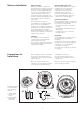


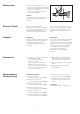


Table Of Contents
- Doku_Standard_Wasser-RK_GB_V09.pdf
- General description
- Important safety measures
- Transport and handling
- Installation
- Electrical connection
- Start-up
- Hydrological data
- Maintenance
- Shutting down / disposing the cooling system
- General fault analysis
- Evaporator pressure
- Compressor is continuously being switched on and off
- No medium circulation
- Appendix
- Datenblatt_060535.pdf
- PID.pdf
- Schaltplan_englisch.pdf
- MPRA-SMK-A-0-Englisch.pdf
- BA_PMA-KS40-1_41-1_42-1_englisch.pdf
- Contents
- 1 Mounting 5
- 2 Electrical connections 6
- 3 Operation 10
- 4 Configuration level 21
- 4.1 Configuration survey 21
- 4.2 Configuration 22
- 4.3 Set-point processing 29
- 4.4 Configuration examples 30
- 4.4.1 On-Off controller / Signaller (inverse) 30
- 4.4.2 2-point controller (inverse) 31
- 4.4.3 3-point controller (relay & relay) 32
- 4.4.4 3-point stepping controller (relay & relay) 33
- 4.4.5 Continuous controller (inverse) 34
- 4.4.6 D - Y - Off controller / 2-point controller with pre-contact 35
- 4.4.7 KS4x-1 with measured value output 36
- 5 Parameter setting level 37
- 6 Calibration level 41
- 7 Programmer 44
- 8 Timer 46
- 9 BlueControl 49
- 10 Versions 50
- 11 Technical data 51
- 12 Safety hints 55
- Index
- Contents
- Parameterliste PMA_english.pdf
- BA_Strömungswächter_SI1000_englisch.pdf
- BA-IFM_Drucksensor PN7009_englisch.pdf
- Endress-Hauser-Display BA188Ra3_englisch.pdf
- Endress-Hauser-Messsonde_BA_englisch.pdf
- BA_FEC12_englisch.pdf

Dimensions (Dimensions in mm)
DC 12 TE
7
DC 12 TE
Rod probe with
reinforced rod for high
lateral load
Left:
fully insulated
Right:
partially insulated
Left:
DC 11 TEN
Fully insulated rod probe
Centre:
DC 16 TEN
Partially insulated rod
probe
Right:
DC 11, 16 TEN
with ground tube
(fully or partially
insulated probe rod)
Left:
DC 21 TEN
Fully insulated rope
probe
Right:
DC 26 TEN
Partially insulated rope
probe
Tensioning weight
with anchor hole
ø8
19
11.5
23
ø21.3
ø6
19
41 AF
41 AF
41 AF
ø10
19
NPT NPTG
G
NPT G
L
2
L
2
L
1
L
1
L
1
L
1
L
1
L
1
Active probe rod
100…3000
Active probe rod
Active probe rod
100…3000
100…3000
Partial insulation
5
ø5
5
ø5
ø2.5
100
100
ø18
19
NPT G
ø4
41 AF
41 AF
110
120
ø22
19
NPT G
L
1
L
1
L
1
L
1
Active part of probe
Active part of probe
~350… 20000
~350… 20000
NPT G
L
2
L
2
41 AF
41
AF
NPT G
ø16
L
1
L
1
L
1
L
1
19
ø12
19
Active probe rod
Active probe rod
100… 3000
100… 3000
Dimensions (Dimensions in mm)
DC 11/16/21/26 TEN
L1 = Length of active probe rod
L2 = Length of partial insulation
minimum: 75 mm
maximum: length L1 minus 50 mm
Thread options: G ¾ A, G 1 A
¾ - 14 NPT, 1 - 11½ NPT
L1 = Length of active probe rod or probe rope
L2 = Length of partial insulation
minimum: 75 mm
maximum: length L1 minus 50 mm
Thread options: G ¾ A, G 1 A
¾ - 14 NPT, 1 -11½ NPT