
Operating instructions


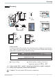


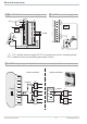
Table Of Contents
- Doku_Standard_Wasser-RK_GB_V09.pdf
- General description
- Important safety measures
- Transport and handling
- Installation
- Electrical connection
- Start-up
- Hydrological data
- Maintenance
- Shutting down / disposing the cooling system
- General fault analysis
- Evaporator pressure
- Compressor is continuously being switched on and off
- No medium circulation
- Appendix
- Datenblatt_060535.pdf
- PID.pdf
- Schaltplan_englisch.pdf
- MPRA-SMK-A-0-Englisch.pdf
- BA_PMA-KS40-1_41-1_42-1_englisch.pdf
- Contents
- 1 Mounting 5
- 2 Electrical connections 6
- 3 Operation 10
- 4 Configuration level 21
- 4.1 Configuration survey 21
- 4.2 Configuration 22
- 4.3 Set-point processing 29
- 4.4 Configuration examples 30
- 4.4.1 On-Off controller / Signaller (inverse) 30
- 4.4.2 2-point controller (inverse) 31
- 4.4.3 3-point controller (relay & relay) 32
- 4.4.4 3-point stepping controller (relay & relay) 33
- 4.4.5 Continuous controller (inverse) 34
- 4.4.6 D - Y - Off controller / 2-point controller with pre-contact 35
- 4.4.7 KS4x-1 with measured value output 36
- 5 Parameter setting level 37
- 6 Calibration level 41
- 7 Programmer 44
- 8 Timer 46
- 9 BlueControl 49
- 10 Versions 50
- 11 Technical data 51
- 12 Safety hints 55
- Index
- Contents
- Parameterliste PMA_english.pdf
- BA_Strömungswächter_SI1000_englisch.pdf
- BA-IFM_Drucksensor PN7009_englisch.pdf
- Endress-Hauser-Display BA188Ra3_englisch.pdf
- Endress-Hauser-Messsonde_BA_englisch.pdf
- BA_FEC12_englisch.pdf

MPR-SMK-A-x-xx-x ENG
Seite 4 von 4
13 911 1452 4 10 1312 15678
16 18 24 26 292017 19 25 2827 3021 22 23
Device
10
Device
9
Device
8
Device
7
Device
6
Device
5
Device
4
Device
3
Device
2
Device
1
10987654321
KS
A2
Faultinputs
Error detection
at “low” signal
Error detection
at“high” signal
K1 K3K2
Sensor
A1 A2
Supply
A1
A1 = Positive operating Voltage / phase L1
A2 = Neutal wire (N)
K1..K3
KS
= Relay contacts
= Relay contact depents on configuration
- Control contact
- Fault contact
- Fault contact and temperature alarm
contact.
Connecting diagram
(the right number of replays are shown of the device label)