
Operating instructions


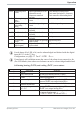


Table Of Contents
- Doku_Standard_Wasser-RK_GB_V09.pdf
- General description
- Important safety measures
- Transport and handling
- Installation
- Electrical connection
- Start-up
- Hydrological data
- Maintenance
- Shutting down / disposing the cooling system
- General fault analysis
- Evaporator pressure
- Compressor is continuously being switched on and off
- No medium circulation
- Appendix
- Datenblatt_060535.pdf
- PID.pdf
- Schaltplan_englisch.pdf
- MPRA-SMK-A-0-Englisch.pdf
- BA_PMA-KS40-1_41-1_42-1_englisch.pdf
- Contents
- 1 Mounting 5
- 2 Electrical connections 6
- 3 Operation 10
- 4 Configuration level 21
- 4.1 Configuration survey 21
- 4.2 Configuration 22
- 4.3 Set-point processing 29
- 4.4 Configuration examples 30
- 4.4.1 On-Off controller / Signaller (inverse) 30
- 4.4.2 2-point controller (inverse) 31
- 4.4.3 3-point controller (relay & relay) 32
- 4.4.4 3-point stepping controller (relay & relay) 33
- 4.4.5 Continuous controller (inverse) 34
- 4.4.6 D - Y - Off controller / 2-point controller with pre-contact 35
- 4.4.7 KS4x-1 with measured value output 36
- 5 Parameter setting level 37
- 6 Calibration level 41
- 7 Programmer 44
- 8 Timer 46
- 9 BlueControl 49
- 10 Versions 50
- 11 Technical data 51
- 12 Safety hints 55
- Index
- Contents
- Parameterliste PMA_english.pdf
- BA_Strömungswächter_SI1000_englisch.pdf
- BA-IFM_Drucksensor PN7009_englisch.pdf
- Endress-Hauser-Display BA188Ra3_englisch.pdf
- Endress-Hauser-Messsonde_BA_englisch.pdf
- BA_FEC12_englisch.pdf

The control parameters can be determined from the values calculated for delay
time T
u
, maximum rate of increase v
max
, control range X
h
and characteristic K
according to the formulas given below. Increase Xp, if line-out to the set-point
oscillates.
3.7 Alarm handling
Max. three alarms can be configured and assigned to the individual outputs. Ge
-
nerally, outputs OuT.1... OuT.3 can be used each for alarm signalling. If more
than one signal is linked to one output the signals are OR linked. Each of the 3 li
-
mit values Lim.1 … Lim.3 has 2 trigger points H.x (Max) and L.x (Min), which
can be switched off individually (parameter = “OFF”). Switching difference
HYS.x of each limit value is adjustable.
Operation
Alarm handling 18 Operating KS4x-1
Formulas
K = Vmax * Tu controller behavior Pb1 [phy. units] td1 [s] ti1 [s]
With 2-point and
3-point controllers,
the cycle time must be
adjusted to
t1 / t2 £ 0,25 * Tu
PID 1,7*K 2*Tu 2*Tu
PD 0,5 * K Tu OFF
PI 2,6 * K OFF 6*Tu
PKOFF OFF
3-point-stepping 1,7 * K Tu 2 * Tu
Parameter adjustment effects
Parameter Control Line-out of disturbances Start-up behaviour
Pb1 higher increased damping slower line-out slower reduction of duty cycle
lower reduced damping faster line-out faster reduction of duty cycle
td1 higher reduced damping faster response to disturbances faster reduction of duty cycle
lower increased damping slower response to disturbances slower reduction of duty cycle
ti1 higher increased damping slower line-out slower reduction of duty cycle
lower reduced damping faster line-out faster reduction of duty cycle