SchaltschrankKühlgerät Cooling unit Climatiseur Koelaggregaat Kylaggregat Condizionatori per armadi di comando Refrigerador para armarios SK 3302.xxx SK 3302.3xx SK 3303.xxx SK 3304.xxx SK 3305.xxx SK 3328.xxx SK 3329.xxx SK 3332.xxx SK 3361.xxx SK 3366.xxx SK 3377.
Contents 1 Notes on documentation. . . . . . . . . . 4 1.1 1.2 1.3 1.4 Associated documents . . . . . . . . . . . . . . . . . CE labelling . . . . . . . . . . . . . . . . . . . . . . . . . . Retention of documents . . . . . . . . . . . . . . . . Symbols used . . . . . . . . . . . . . . . . . . . . . . . . 4 4 4 4 2 Safety instructions. . . . . . . . . . . . . . . 4 3 Device description . . . . . . . . . . . . . . . 5 3.1 3.1.1 3.1.2 3.1.3 3.1.4 3.1.5 3.1.6 3.1.7 3.1.8 3.2 3.3 Functional description . .
1 Notes on documentation 1 EN Notes on documentation These assembly instructions are aimed at tradespersons who are familiar with assembly and installation of the cooling unit, and at trained specialists who are familiar with operation of the cooling unit. 1.
3 Device description 3 Device description Depending on the model chosen, your cooling unit may vary in appearance from the illustrations contained in these instructions. However, the functions are identical in principle. into the hermetically sealed cooling circuit provides effective protection against moisture, acid, dirt particles, and foreign bodies within the cooling circuit.
3 Device description EN 3.1.4 Safety equipment – In the cooling cycle, the cooling unit has a tested pressure-operated switch to EN 12 263 which is set to maximum PS (admissible pressure); this operates via an automatic reset device whenever the pressure drops again. – Temperature monitoring prevents the evaporator coil from icing over. If there is a risk of icing, the compressor switches itself off and automatically switches itself back on again at higher temperatures.
4 Assembly and connection 3.1.8 Additional interface X3 Note: The electrical signals at the interface are of an extra-low voltage (not extra-low safety voltages to EN 60 335). An additional interface card may be connected to the 9-pole SUB-D connector X3 in order to incorporate the cooling unit into higher-level monitoring systems (available as an accessory, interface card Model No. SK 324.200). 3.
4 Assembly and connection EN 4.2.2 Layout of the electronic components in the enclosure Caution! Risk of condensation! When arranging the components inside the enclosure, please ensure that the cold airflow from the cooling unit is not directed at active components. Please also ensure that the cold airflow is not directed at the warm exhaust airflow from active components such as converters.
4 Assembly and connection 4.3.1 Cutting out the enclosure • Stick the supplied drilling template onto the side panel or door of the enclosure using adhesive tape. There are dimensioning lines on the drilling template to suit the various installation options for your cooling unit. • Using the dimension drawings (see Appendix), identify the valid lines and dimensions for your installation type on the drilling template.
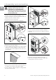
4 Assembly and connection Risk of damage! Stability of the cooling unit is only guaranteed in its assembled state. Brace the rear enclosure half to prevent it from falling over before removing the front enclosure half. EN • Loosen the four nuts on the front enclosure half and pull the enclosure forwards by approx. 5 cm. • Loosen the flat-pin connectors of the PE conductor between the two enclosure halves. • Disconnect the fan connection. • Remove the front enclosure tray completely. Fig.
4 Assembly and connection 4.3.4 Full internal mounting of the cooling unit • Carefully remove the louvred grille and the infill panel from the enclosure by pulling forwards. • Carefully disconnect the connector from the rear of the display. EN Fig. 17: Fig. 15: Remove the louvred grille and disconnect the display • Cut the supplied sealing tape to the correct length and stick it carefully along the front enclosure half so that no gaps are left at the connection points. Fig.
4 Assembly and connection 4.5 Notes on electrical installation EN When performing the electrical installation, it is important to observe all valid national and regional regulations as well as the provisions of the responsible power supply company. Electrical installation must only be carried out by a qualified electrician who is responsible for compliance with the existing standards and regulations. 4.5.
4 Assembly and connection 4.6 Carrying out the electrical installation 4.6.1 Bus connection (only in conjunction with several units with a Comfort controller) When using several cooling units, the serial device interface X2 can be used to connect up to ten cooling units with the bus cable (Model No. SK 3124.100). 4.6.2 Connection X3 for serial interface The interface card (Model No. SK 3124.200) may be connected to X3.
4 Assembly and connection EN CMC 1 I/O unit 2 RTT Master Adr.: 09 RTT Slave Adr.: 11 X3 St. X2 Adr.: 12 X3 Bu. X2 X3 X2 RTT Slave Adr.: 19 X1 X1 X1 X2 RTT Slave X1 X3 St. X2 St. X2 X3 X2 St. X2 X2 X2 X2 X2 X2 Bu. St. Bu. St. Bu. 3 Fig. 19: Connection example: Master-slave operation Legend 1 Serial interface (Model No. SK 3124.200) 2 Serial interface cable 3 Master-slave bus cable (Model No. SK 3124.
4 Assembly and connection EN SK 3302.100/.110, SK 3303.100/.110, SK 3302.200/.210, SK 3303.200/.210, SK 3302.300/.310, SK 3361.100/.110, SK 3361.200/.210 21 PE 5 Mains A2 22 S1 L1 X1 L2 N 1 PE 1 2 3 L N Power L1 2 1 3 2 5 4 3 R1 L2 2 1 NTC I red S1 NTC E blue Kx Term A1 2 B1 2 B2 8 2 F2 1 M2 1 2 3 M1 1 2 3 P M4 1 2 3 F2 C4 C1 S R C2 C M M 1~ 1~ M2 M4 F3 M1 Fig. 21: Electrical wiring plan no. 1 21 SK 3303.500/.510, SK 3303.600/.610, SK 3361.500/.
4 Assembly and connection EN SK 3361.540/.640 L2 T1 S1 22 400 V A2 230 V PE 5 PE 21 L1 L2 N L1 X1 2 1 PE 4 3 5 X2 X3 3 1 2 3 L 1 N S1 3 2 2 2 1 Power B1 NTC I red Serial MS1 K1 K2 8 2 B2 NTC E blue Kx 2 B3 NTC C white PE 2 B4 NTC A yellow A1 2 B5 Level green 4 Term M4 1 2 3 M2 1 2 3 M1 1 2 3 2 1 F2 P F2 C4 PE C1 S R C2 M C F3 M 1~ 1~ M2 M4 M1 Fig. 23: Electrical wiring plan no. 3 21 SK 3304.100/.
4 Assembly and connection EN 21 SK 3305.100/.110, SK 3328.100/.110, SK 3329.100/.110, SK 3305.200/.210, SK 3328.200/.210, SK 3329.200/.210, SK 3366.100/.110, SK 3377.100/.110, SK 3366.200/.210, SK 3377.200/.210 Mains 22 S1 PE 5 L1 L2 N L1 X1 1 PE 2 3 5 4 L1 F11 L2 R1 L2 A2 E1 T1 L N 1 2 3 PE 1 L N Power 2 3 2 1 S1 M2 1 2 3 M1 1 2 3 F2 C4 4 C12 1 C11 2 5 C2 Fig.
4 Assembly and connection EN 21 SK 3304.700, SK 3328.700 S1 22 Mains PE L1 L2 N 5 L1 X1 L1 T1 F12 PE N 1 2 3 A2 5 4 L1 F11 L1 L2/N F11 L2 R1 L2 E1 E1 1 2 3 123 L N Power PE 1 2 3 2 1 2 NTC I red Kx B2 8 Term A1 B1 2 NTC E blue S1 2 F2 P F2 1 M2 1 2 3 M1 1 2 3 A C1.2 P F3 Fig. 27: A3 4 1 R C M4 1 2 3 C1.1 2 5 M1 M 1~ M 1~ M2 M4 Electrical wiring plan no. 7 21 SK 3304.800, SK 3328.
4 Assembly and connection EN 21 SK 3304.500/.600 S1 Mains 22 PE X2 5 X1 L2 L1 L1 L2 L N 1 PE N 2 3 X3 A2 5 4 3 6 F11 T1 E1 PE 1 2 3 1 L S1 N 2 3 2 1 MS1 2 NTC I red Serial Power K1 K2 M4 1 2 3 F2 B5 4 Term M2 1 2 3 B4 2 Level green M1 1 2 3 B3 2 NTC A yellow A1 B2 2 NTC C white Kx B1 2 NTC E blue 2 1 P F2 C1 C4 1 R S C2 F3 3 M 1~ M2 M4 C M1 Fig. 29: M 1~ Electrical wiring plan no. 9 21 SK 3305.500/.510, SK 3328.500/.510, SK 3329.
4 Assembly and connection EN SK 3304.540, SK 3304.542, SK 3305.540, SK 3305.542, SK 3328.540, SK 3329.540, SK 3304.640, SK 3305.640, SK 3328.640, SK 3329.640, SK 3366.540, SK 3377.540, SK 3366.640, SK 3377.
4 Assembly and connection EN 21 SK 3332.540/.640 S1 22 Mains A2 PE X1 6 L1 L2 L3 PE 1 2 3 X3 X2 5 4 3 8 F11 F12 E1 T1 3 R 2 S 1 1 2 2 4 1 3 MS1 T K2 NTC I red Serial NTC E blue S1 Power 2 2 K1 NTC C white Kx 2 2 NTC A yellow Level green A1 Term M1 F3 1 2 3 4 1 2 3 U V F2 F4 M2 4 1 2 3 4 1 2 3 M4 F5 1 2 3 1 2 B1 B2 B3 B4 B5 4 2 F2 M M P 3~ 3~ M2 M4 W M1 Fig. 33: Electrical wiring plan no.
5 Commissioning 4.7 Finalising assembly EN 4.7.1 Installing the filter media The cooling unit condenser is finished all over with a dirt-repelling, easy-to-clean RiNano coating. In many cases, therefore, the use of filter media is unnecessary, particularly in the case of dry dusts. For dry, coarse dust and lint in the ambient air, we recommend installing an additional PU foam filter mat (available as an accessory) in the cooling unit.
6 Operation 6 Operation You can operate the cooling unit using the controller on the front of the device (Fig. 1, no. 11, page 5). Depending on the model, the unit is equipped with a Basic or Comfort controller. 6.1 Control using the Basic controller For unit types SK xxxx.100/.110/.140 and SK xxxx.200/.210/.240/.300/.310. 1 3 4 2 5 Fig.
6 Operation EN 6.1.2 Operating and error display The Basic controller monitors and controls the cooling unit. It indicates the operating and error status via the green and red LEDs (Fig. 36, no. 3 and 4): LED Status Cause Solution Green (line) Illuminated Voltage present, unit operational – Flashing Only with door limit switch installed: Enclosure door open In order to avoid condensation, close the enclosure door as quickly as possible.
6 Operation The overtemperature message (red LED illuminated) may also be polled via an integral floating contact on the connection clamp of the cooling unit (system message relay with changeover contact, see connection diagrams under “4.6.3 Installing the power supply”, page 14): – Terminal 3: NC (normally closed) – Terminal 4: C (connection of the supply voltage to the system message relay) – Terminal 5: NO (normally open) The NC and NO definitions refer to the de-energised state.
6 Operation 6.2 Control using the Comfort controller EN For unit types SK xxxx.500/.510/.540 and SK xxxx.600/.610/.640. 1 4 Fig. 38: 2 3 Comfort controller Legend 1 Programming button, also display of the set temperature unit (degrees Celsius) 2 Set button 3 Programming button, also display of the set temperature unit (degrees Fahrenheit) 4 7-segment display 6.2.
6 Operation In principle, the programming is identical for all editable parameters. To enter programming mode: • Press button 2 (“Set”) for approx. 5 sec. The controller is now in programming mode. While in programming mode, if you do not press any buttons for approx. 30 sec., the display will first flash, then the controller will switch back to normal display mode. The “Esc” display indicates that any made changes have not been saved.
6 Operation 6.2.5 Programming overview = 5 sec. = 5 sec. EN Fig.
6 Operation 6.2.6 Defining system messages for evaluation System messages are shown on the display screen of the Comfort controller via the displays A1 to A20 and E0. A more detailed explanation of the system messages may be found in section “6.2.8 Evaluating system messages”, page 30. See also Fig. 39 on page 28. Progr. level Display screen Min. value Max.
6 Operation EN 6.2.7 Setting the master-slave identifier When several cooling units are connected together (maximum ten), one of the cooling units must be defined as the “master” and the others as “slaves”. For this purpose, assign a corresponding identifier (address) to each cooling unit which will enable the cooling unit to be identified in the network.
6 Operation Display screen A01 System message Possible cause Measures to rectify the fault Enclosure door open Door open or door limit switch incorrectly positioned Close door, position door limit switch correctly, check connection if necessary A02 Internal temperature of enclosure too high A03 Filter monitoring A04 Ambient temperature too high/too low Icing hazard Cooling capacity inadequate/unit undersized. Check cooling capacity Error as a consequence of messages A03 to A17.
7 Inspection and maintenance EN 6.2.9 Resetting the Comfort controller After the occurrence of faults A03, A06 and A07, you will need to reset the Comfort controller. • Press buttons 1 (▲) and 3 (▼) (Fig. 38) simultaneously for 5 sec. The system messages will disappear and the temperature display will be shown. 7 7.1.1 Compressed air cleaning SK 3304.xxx, SK 3305.xxx Inspection and maintenance Risk of electric shock! The unit is live.
7 Inspection and maintenance EN Fig. 43: Fig. 44: Remove the lower louvred grille Fig. 45: Disconnect the connector from the display (1) Fig.
7 Inspection and maintenance EN Fig. 50: Disconnect the fan connectors Fig. 47: Cooling unit without grille Fig. 51: Remove the cover (loosen the four screws) Fig. 48: Remove the external circuit fan (loosen the four screws) Fig. 52: Push back the display cable Fig. 49: Remove the fan Fig.
7 Inspection and maintenance EN Fig. 54: Fig. 55: Fig. 56: Loosen the earthing cable between the cover and the chassis (1) Fig. 57: Loosen the earthing cable between the cover and the chassis (2) Fig.
7 Inspection and maintenance EN Fig. 59: Clean out the heat exchanger coil and compressor chamber using compressed air (2) Fig. 61: Remove the upper louvred grille (1) Fig. 62: Remove the upper louvred grille (2) 7.1.2 Compressed air cleaning SK 3328.xxx, SK 3329.xxx, SK 3332.xxx Fig.
7 Inspection and maintenance EN Fig. 63: Remove the upper louvred grille (3) Fig. 65: Remove the lower louvred grille (2) Fig. 64: Remove the lower louvred grille (1) Fig.
7 Inspection and maintenance EN Fig. 67: Disconnect the display cable Fig. 71: Remove the external circuit fan Fig. 68: Push back the display cable and press it through the cable gland (1) Fig. 72: Disconnect the fan connectors (1) Fig. 69: Push back the display cable and press it through the cable gland (2) Fig. 73: Disconnect the fan connectors (2) Fig. 70: Loosen the four screws of the external circuit fan Fig.
7 Inspection and maintenance EN Fig. 75: Disconnect the fan earthing cable (1) Fig. 76: Disconnect the fan earthing cable (2) Fig. 78: Remove the cover Fig. 77: Loosen the four screws of the cover Fig.
7 Inspection and maintenance EN Fig. 80: Disconnect the earthing cable (2) Fig. 82: Clean out the heat exchanger coil and compressor chamber using compressed air (2) Fig. 81: Clean out the heat exchanger coil and compressor chamber using compressed air (1) Fig.
8 Storage and disposal 8 Storage and disposal 9 Technical specifications EN Caution! Risk of damage! The cooling unit must not be subjected to temperatures above +70°C during storage. During storage, the cooling unit must stand upright. The closed cooling circuit contains refrigerant and oil which must be properly disposed of for the sake of the environment. Disposal can be performed at the RITTAL plant. Please contact us for advice. Fig.
9 Technical specifications EN Unit Model No. SK Basic controller, RAL 7035 – 3302.100 3302.110 3302.300 3302.310 3303.100 3303.110 3304.100 3304.110 3304.700 Comfort controller, RAL 7035 – – – – – 3303.500 3303.510 3304.500 3304.510 3304.800 Basic controller, stainless steel cover – 3302.200 3302.210 – – 3303.200 3303.210 3304.200 3304.210 – Comfort controller, stainless steel cover – – – – – 3303.600 3303.610 3304.600 3304.
9 Technical specifications Unit Basic controller, RAL 7035 Model No. SK – 3304.140 3304.142 3305.100 Comfort controller, RAL 7035 – 3304.540 3304.542 Basic controller, stainless steel cover – Comfort controller, stainless steel cover – Rated voltage V, Hz Rated current A 3305.110 3305.140 3305.142 3328.100 3328.110 3328.140 3329.100 3328.700 3305.500 3305.510 3305.540 3305.542 3328.500 3328.510 3328.540 3329.500 3328.800 3304.240 3305.200 3305.210 3305.240 3328.200 3328.
9 Technical specifications Model No. SK Unit EN Basic controller, RAL 7035 – 3329.110 3329.140 3332.140 3361.100 3361.110 3361.140 Comfort controller, RAL 7035 – 3329.510 3329.540 3332.540 3361.500 3361.510 3361.540 Basic controller, stainless steel cover – 3329.210 3329.240 3332.240 3361.200 3361.210 3361.240 Comfort controller, stainless steel cover – 3329.610 3329.640 3332.640 3361.600 3361.610 3361.
10 List of spare parts 10 List of spare parts EN 75 SK 3302.xxx 40 10 71 25 45 1 100 55 71 90 15 5 Fig. 85: Spare parts for SK 3302.xxx SK 3302.3xx 10 90 71 20 71 25 100 45 40 1 5 15 55 Fig. 86: Spare parts for SK 3302.
10 List of spare parts EN SK 3303.xxx SK 3361.xxx 10 40 71 30 75 25 1 45 15 55 100 90 5 71 71 20 71 Fig. 87: Spare parts for SK 3303.xxx, SK 3361.xxx SK 3304.xxx SK 3305.xxx 10 40 71 30 102 75 1 45 25 100 71 50 80 15 20 55 90 45 5 71 71 101 Fig. 88: 46 Spare parts for SK 3304.xxx, SK 3305.
10 List of spare parts 75 SK 3328.xxx SK 3329.xxx EN 10 40 46 71 30 102 45 71 20 50 1 55 100 45 46 90 80 5 71 71 15 101 Fig. 89: Spare parts for SK 3328.xxx, SK 3329.xxx 75 SK 3332.xxx 10 46 40 71 102 45 25 100 50 55 1 45 71 90 46 71 71 20 15 5 30 101 Fig. 90: Spare parts for SK 3332.
10 List of spare parts EN SK 3366.xxx SK 3377.xxx 75 75 100 40 46 10 71 102 45 20 90 50 30 71 55 1 25 45 101 46 5 80 15 Fig. 91: Spare parts for SK 3366.xxx, SK 3377.
11 Appendix: Cut-out and hole sizes 11 Appendix: Cut-out and hole sizes 353 11.1 Dimensions for external mounting EN 55 345 240 78.5 354 326 251 360 280 140 85.5 Fig. 95: 49 Ø8 155 (10x) 260 354 165.5 550 501 353 360 354 354 SK 3366.xxx, SK 3377.xxx external mounting 250 350 260 280 34.5 SK 3302.xxx external mounting (except SK 3302.3xx) 255 400 Fig. 92: 525 6 385 350 281 340 950 Ø 9.5 (8x) 255 153 471 25 15 350 Fig. 96: Fig. 93: SK 3304.xxx, SK 3305.
11 Appendix: Cut-out and hole sizes 400 500 370 340 380 145 440 380 320 145 R9.5 (2x) 1580 500 330 45 EN 1580 1540 1558 1554 25 Fig. 98: 376 275 375 440 360 164 Ø 13 (10x) Ø 13 (4x) SK 3332.xxx external mounting R9.5 (2x) 11.2 Dimensions for partial internal mounting 320 Fig. 101: SK 3328.xxx, SK 3329.xxx partial internal mounting 280 100 20 254 100 500 25 145 195 550 497 266 523 524 362 18 x 45° 1580 474 1530 1550 Ø 8 (4x) (230) Fig. 99: SK 3303.
11 Appendix: Cut-out and hole sizes 11.3 Dimensions for full internal mounting 98 280 210 370 25 R6 (4x) 25 200 EN 400 42 254 25 x 45 2 50 920 950 920 550 266 518 492 524 Ø 15 (2x) 380 Ø 8 (4x) 18 x 45° Ø 9.5 (4x) (230) Fig. 103: SK 3302.1xx full internal mounting 98 55 Fig. 106: SK 3304.xxx, SK 3305.xxx full internal mounting 525 400 20 510 370 240 50 R9.5 (2x) 325 20 x 45° 314 340 320 Ø 7.5 (4x) Fig. 104: SK 3302.
Schaltschrank-Systeme Industrial Enclosures Coffrets et armoires électriques Kastsystemen Apparatskåpssystem Armadi per quadri di comando Sistemas de armarios Stromverteilung Power Distribution Distribution de courant Stroomverdeling Strömfördelning Distribuzione di corrente Distribución de corriente Elektronik-Aufbau-Systeme Electronic Packaging Electronique Electronic Packaging Systems Electronic Packaging Contenitori per elettronica Sistemas para la electrónica System-Klimatisierung System Climate Con