
Operating instructions


12 RITTAL cooling unit assembly and operating instructions
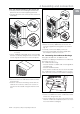
4 Assembly and connection
EN
4.5 Notes on electrical installation
When performing the electrical installation, it is im-
portant to observe all valid national and regional reg-
ulations as well as the provisions of the responsible
power supply company. Electrical installation must
only be carried out by a qualified electrician who is re-
sponsible for compliance with the existing standards
and regulations.
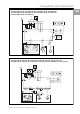
4.5.1 Connection data
– The connected voltage and frequency must
correspond to the values stated on the rating plate.
– The cooling unit must be connected to the mains
via an all-pin isolating device, which ensures at
least 3 mm contact opening when switched off.
– No additional temperature control may be connec-
ted upstream of the unit at the supply end.
– Install the pre-fuse specified on the rating plate
to protect the cable and equipment from short-
circuits.
– The mains connection must ensure low-noise
potential equalisation.
4.5.2 Overvoltage protection and supply line
load
– The unit does not have its own overvoltage pro-
tection. Measures must be taken by the operator at
the supply end to ensure effective lightning and
overvoltage protection. The mains voltage must not
exceed a tolerance of ±10%.
– In accordance with IEC 61 000-3-11, the unit is
intended solely for use at sites with a continuous
current-carrying capacity (incoming mains power
supply) of more than 100 A per phase and with
a supply voltage of 400/230 V. If necessary, the
power supply company must be consulted to
ensure that the continuous current-carrying capa-
city at the point of connection to the public grid is
sufficient for connection of such a unit.
– The fans and compressors in single- and three-
phase units are intrinsically safe (thermal winding
protection). The same also applies to the transfor-
mer versions of types SK 3304.110, SK 3304.510,
SK 3305.110, SK 3305.510, SK 3328.110,
SK 3328.510, SK 3329.110 and SK 3329.510
and to special-voltage units which are likewise
equipped with a transformer.
– Install the slow pre-fuse specified on the rating
plate (miniature circuit-breaker with “K” charac-
teristic, circuit-breaker for plant or transformer
protection) to protect the cable and equipment from
short-circuits. Select a suitable circuit-breaker in
accordance with the information specified on the
rating plate: Set it to the minimum specified value.
This will achieve the best short-circuit protection for
cables and equipment.
Example: Specified setting range 6.3 – 10 A;
set to 6.3 A.
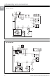
4.5.3 Three-phase devices
– The three-phase version of models SK 3304.xxx,
SK 3305.xxx, SK 3328.xxx, SK 3329.xxx and
SK 3332.xxx must be connected to a TN network
with star earthing via a circuit-breaker for plant
protection (current setting as per the rating plate).
Three-phase units with special voltages must be
protected with a circuit-breaker for transformer
protection (category AC-3) as per the rating plate.
– Units designed for three phase 400/460 V feature
additional monitoring of the rotary field or the
absence of a phase. If the rotary field is incorrect or
a phase is absent, the unit will not run.
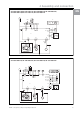
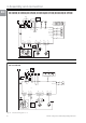
4.5.4 Door limit switch
– Each door limit switch must only be assigned to one
cooling unit.
– Several door limit switches may be connected in
parallel and operated on one cooling unit.
– The minimum cross-section for the connection
cable is 0.3 mm
2
for a cable length of 2 m.
– The line resistance to the door limit switch must not
exceed a maximum of 50
Ω
.
– The door limit switch only supports a floating
connection; no external voltages.
– The contact of the door limit switch must be closed
when the door is open.
The safety extra-low voltage for the door limit switch
is
provided by the internal power pack: Current
approx. 30 mA DC.
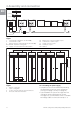
• Connect the door limit switch to terminals 1 and 2 of
the connector.
4.5.5 Notes on the flicker standard
The flicker limits specified in standard EN 61 000-3-3
or -3-11 are adhered to, provided the supply im-
pedance is less than approx. 1.5
Ω
.
Where necessary, the unit operator should measure
the connected impedance or consult the responsible
power supply company. If there is no way of influenc-
ing the supply impedance and sensitive installed
components (e.g. BUS) are subjected to interference,
a line reactor or starting-current limiting device should
be connected upstream of the cooling unit to restrict
the startup current of the cooling unit.
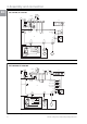
4.5.6 Potential equalisation
RITTAL recommends connecting a conductor with a
nominal cross-section of at least 6 mm
2
to the poten-
tial equalisation connection point on wall-mounted
cooling units, and incorporating it into the existing po-
tential equalisation system.
According to the standard, the PE conductor in the
mains connection cable is not classified as an equi-
potential bonding conductor.