
Instructions / Assembly


READ & SAVE
INSTALLATION & OPERATION INSTRUCTIONS
TOOLS & MATERIALS REQUIRED
Adjustable wrench
Flat Blade screw driver
Step Ladder
Wire cutters
Wiring supplies as required by electrical code
CAUTION: Before assembling your Lighting fixture,
refer to the section titled ELECTRICAL
CONNECTIONS. If you feel you do not have
electrical wiring experience, refer to a do-it yourself
wiring handbook or have your fixture installed by a
qualified licensed electrician.
GENERAL
1. To ensure the success of the installation, be sure to
read these instructions and review the diagrams
before beginning.
2. All electrical connections must be in accordance
with local codes, ordinances, or the National
Electrical Code. If you are unfamiliar with methods
of installing electrical wiring, secure the services of a
qualified licensed electrician.
3. These fixtures are intended to be mounted to a 4” x
4” x 2-1/8” deep metal octagon outlet box. The box
must be directly supported by the building structure.
4. Before starting the installation, disconnect the
power by turning off the circuit breaker of by
removing the fuse at the fuse box. Turning the power
off using the light switch is not sufficient to prevent
electrical shock.
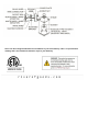
PREPARE THE FIXTURE
NOTE: FIRST TURN OFF ELECTRICITY
Refer to figure 1 for illustration of fixture parts and
assembly.
1. If you are replacing an existing fixture, disconnect
and remove the old fixture. Expose the supply wiring
from the outlet box.
2. Yout fixture is supplied with two machine screws,
thread the machine screws into the opposite side of
the mounting bracket. The long end of the machine
screws should be facing toward the room.
3. Fasten the mounting bracket to the outlet box using
the two screws supplied.
4. Push white and black wire through mounting
bracket
5. Attach grounding wire (green or bare copper) from
the supply circuit to the mounting bracket with the
green grounding attachment screw provided.
6. Make electrical connections - SEE BELOW.
ELECTRICAL CONNECTIONS
Required Supply Circuit: 120V, 60 Hz
First proceed by identifying the wires on your
luminary: The POSITIVE wire can be identified by
its color (Black Wire), and the NEGATIVE wire can
be identified by its color (White Wire).
Connect the luminary POSITIVE wire to the BLACK
wire of the supply circuit. Next, connect the
NEGATIVE wire of your luminary to the WHITE
(neutral) wire of the supply circuit. Connect the
green (or bare copper) colored wire from the supply
circuit to the GREEN GROUND SCREW located
on the MOUNTING BRACKET (see figure).
Use UL/CSA Listed wire connectors (included)
suitable for the size, type and number of
conductors. No loose strands or loose connections
should be present. Secure wire connectors with
UL/CSA Listed electrical tape.
FINAL ASSEMBLY
1. Spread the electrical splices so that the black wires
are on one side of the outlet box and the white wires
are on the other side.
2.Place the fixture against the mounting surface
allowing the machine screws to pass through the
cover plate. Secure with the decorative nuts provided.
3. Install bulbs (not provided).
4. If applicable, attach shade to the threaded stem,
and then secure with finial.
5. Restore electricity and check the operation of your
lighting fixture.
MADE IN CHINA