
User Manual


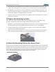
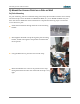
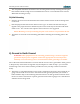
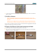
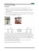

Table Of Contents
- 1) You Need the Following Items
- 2) Choose a Suitable Location
- 3) Prepare the Mounting Location
- 4) Attach the Mounting Plate to the Access Point
- 5) Mount the Access Point on a Pole or Wall
- 6) Ground to Earth Ground
- 7) Install an Antenna
- 8) Prepare the Ethernet Cable with the Waterproof Shell
- 9) Connect the Cables
- 10) Log In to the Access Point
- 11) Configure the Access Point
- 12) Secure Low Level Access to the Access Point
- Drawings
- Customer Support
- Notices, Warnings, & Compliance Statements
- 未命名

XR520H Quick Installation Guide
The maximum cable length between the XR520H and the RJ-45 Ethernet Network is 100
meters. The PoGE Injector is not a repeater, so its location will not increase this distance.
The XR520H can operate from a Wireless Distribution System (WDS) link. However, the
unit will need to be configured via the Ethernet connection prior to mounting and power
must still be supplied via the RJ-45 Ethernet connector.
Keep the unit away from electrical devices or appliances that generate RF noise—at least 3
to 6 feet (1 to 2 meters).
3) Prepare the Mounting Location
Part of the mechanical installation is to ensure that the Access Point is grounded to earth
ground to dissipate any static electric charge that may develop due to wind.
Determine a good electrical earth ground point near the Access Point mounting location. If
an earth ground point is not available, consult an electrician to have one installed.
Crimp a terminal lug to a sufficient length of 16 gauge wire to reach from the mounted
Access Point to the earth ground point.
Before the Access Point is attached to a wall or pole, secure the terminal lug to the Access
Point with the #6 screw provided in the location indicated by the white arrow, below..
4) Attach the Mounting Plate to the Access Point
The accessory kit includes a small mounting plate. Mounting plate dimensions are included in
the Drawings section at the end of this guide. The mounting plate can be used for wall or pole
mounting by reversing the side of the plate exposed. Attach the mounting plate to the Access
Point using the eight provided screws in the locations indicated below (secure in at least 4
places). The Pole Mounting position of the bracket is shown below.
For Pole Mounting:
For Wall Mounting:
- 2 -