
User Manual


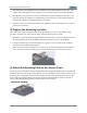
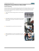
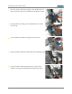
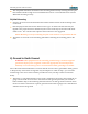
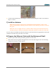

Table Of Contents
- 1) You Need the Following Items
- 2) Choose a Suitable Location
- 3) Prepare the Mounting Location
- 4) Attach the Mounting Plate to the Access Point
- 5) Mount the Access Point on a Pole or Wall
- 6) Ground to Earth Ground
- 7) Install an Antenna
- 8) Prepare the Ethernet Cable with the Waterproof Shell
- 9) Connect the Cables
- 10) Log In to the Access Point
- 11) Configure the Access Point
- 12) Secure Low Level Access to the Access Point
- Drawings
- Customer Support
- Notices, Warnings, & Compliance Statements
- 未命名

XR520H Quick Installation Guide
The completed attachment should have the mounting bracket firmly seated against the pole.
One band should be enough for most installations however a second band can be used for
additional mounting security.
5b) Wall Mounting
Place the Access Point in the desired location and mark the location of the mounting holes
on the wall.
Drill and prepare the holes for the desired screw type. In metal walls the holes may be
tapped to the proper thread or alternatively the Access Point may be mounted with sheet
metal screws. For concrete walls a plastic anchor and screw are suggested.
NOTE: Mounting screws for attaching the plate to the wall are not provided in the kit.
Attach the Access Point to the mounting plate before attaching the mounting plate to the
wall.
6) Ground to Earth Ground
WARNING: This equipment must be externally grounded using a customer-supplied
ground wire before power is applied. Contact the appropriate electrical inspection
authority or an electrician if you are uncertain that suitable grounding is available.
Part of the mechanical installation is to insure that the Access Point is grounded to earth ground
to dissipate any static electric charge that may develop due to wind. In Step 3, you secured a
terminal lug to the Access Point with the provided #6 screw (see Step 3 if this has not been
done).
After Step 3 is completed and the Access Point is mounted to the wall or pole, attach the 16
gauge wire from the Access Point to the electrical earth ground point that you located or
had installed in Step 3. The following illustration shows an earth ground connection where
the Access Point is mounted on a pole at ground level and the 16 gauge wire is attached to a
stake driven into the ground.
- 5 -