
User Manual


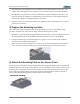
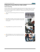
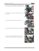
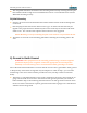
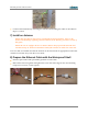
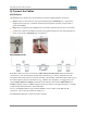

Table Of Contents
- 1) You Need the Following Items
- 2) Choose a Suitable Location
- 3) Prepare the Mounting Location
- 4) Attach the Mounting Plate to the Access Point
- 5) Mount the Access Point on a Pole or Wall
- 6) Ground to Earth Ground
- 7) Install an Antenna
- 8) Prepare the Ethernet Cable with the Waterproof Shell
- 9) Connect the Cables
- 10) Log In to the Access Point
- 11) Configure the Access Point
- 12) Secure Low Level Access to the Access Point
- Drawings
- Customer Support
- Notices, Warnings, & Compliance Statements
- 未命名

XR520H Quick Installation Guide
9) Connect the Cables
9a) POE port
All XR520H Access Points are powered directly via their Gigabit Ethernet connection.
Power: These Access Points are only powered through the GIG POE port. Only Xirrus-
supplied power injectors, or 802.3af or 802.3at PoE-compliant switches, may be used to
power the XR520H.
Data: Data is supplied to the Gigabit port via the same cable that powers the Access Point.
Connect the outdoor-rated Ethernet cable carrying data and power from the PoGE injector
to the Access Point’s GIG POE port as indicated.
9b) Antenna ports
Both IAP1 cables from the Access Point (IAP1 ANT1 and IAP1 ANT2) must be attached to
connectors for the same frequency band on the antenna (e.g., 2.4GHz), and IAP1 must be
assigned to that band on the Access Point (see Step 11). Similarly, both IAP2 cables need to go to
the other frequency band on the antenna (e.g., 5.8GHz). For simplicity, we suggest that you
connect IAP1 (ANT1 and ANT2) to 2.4GHz on the antenna, and connect IAP2 (ANT1 and
ANT2) to 5.8GHz. Then you must configure the Access Point to correspond in Step 11: set IAP1
to the 2.4GHz band and IAP2 to the 5GHz band.
To use a 3x3 MIMO antenna type with the XR520H, connect cables to the +45 and -45
connectors. Do not use the connector marked “V”.
The XR520H has RP-TNC connectors for the antenna.
- 7 -