
Data Sheet


©
RVT28AEFNWR00
Rev.1.2
Figure 2. Measuring method for Contrast ratio, surface luminance, Luminance uniformity, CIE (x, y) chromaticity
Figure 3.The definition of viewing angle
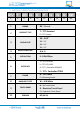
7 INTERFACE DESCRIPTION
PIN NO.
SYMBOL
DESCRIPTION
1
VDD
Power Supply
2
GND
Ground
3
SPI_SCLK/ I2C_SCL
SPI SCK Signal / I2C SCL Signal, Internally 47k Pull UP
4
MISO/ I2C_SDA
SPI MISO Signal / I2C SDA Signal, Internally 47k Pull UP
5
MOSI/ I2C_SA0
SPI MOSI Signal / I2C Slave Address Bit 0, Internally 47k Pull UP
6
CS/I2C_SA1
SPI Chip Select Signal / I2C Slave Address Bit 1, Internally 47k Pull UP
7
INT
Interrupt Signal, Active Low, Internally 47k Pull UP
8
PD
Power Down Signal, Active Low, Internally 47k Pull UP
9
MODE
Host Interface SPI(Pull Low) or I2C(Pull Up) Mode Select
Input, Internally 10k Pull DOWN
10
AUDIO_OUT
Audio Out Signal
11
NC
Not Connected
12
NC
Not Connected
13
NC
Not Connected
14
NC
Not Connected
15
NC
Not Connected
16
NC
Not Connected
17
BLVDD
Backlight Power Supply, Can Be Connected to VDD
18
BLVDD
Backlight Power Supply, Can Be Connected to VDD
19
BLGND
Backlight Ground, Internally connected to GND
20
BLGND
Backlight Ground, Internally connected to GND