Operator's Manual WE ARE HUNTERS LOCKDOWN™ 21 1-MAN Ladder Stand MODEL RE651 Maximum Height 21' to shooting rail Maximum Field Rating 300 lbs Tree Diameter Range 12" to 20" Wear Your Harness! PRODUCT MEETS INDUSTRY STANDARDS RECOGNIZED BY Get parts online at www.HuntRiversEdge.
Operator's Manual LOCKDOWN 21 1-MAN Ladder Stand INTRODUCTION Rivers Edge® Treestands are engineered with you the hunter in mind. We appreciate your purchase of one of our world class treestands. Follow these few simple instructions and your stand will provide you many years of trouble-free pleasure. Instructions should be kept in a safe place and reviewed at least annually.
Operator's Manual LOCKDOWN 21 1-MAN Ladder Stand STOP READ AND UNDERSTAND THE FOLLOWING WARNINGS BEFORE ASSEMBLY MODEL RE651 MAXIMUM USE HEIGHT - 21' TO SHOOTING RAIL MAXIMUM OCCUPANCY - ONE (1) TOTAL WEIGHT LIMIT - 300 LB TREE DIAMETER RANGE - 12” TO 20” WARNING This product carries strict height and weight restrictions. Do Not use this product if you exceed the total weight limit. Please note that the total weight limit includes the user(s) and their equipment.
Operator's Manual LOCKDOWN 21 1-MAN Ladder Stand WARNING INSPECTION AND MAINTENANCE Always lean forward as you climb and attach your harness to the tree before securing the platform to the tree and stepping onto the platform. BEFORE EACH USE PERFORM THE FOLLOWING: Never exceed the stated maximum use height. • Inspect all webbing, rope, cord, and strap assemblies for wear or damage.
Bolts shown are for size reference. Extra hardware may be included in the parts bag.
Operator's Manual LOCKDOWN 21 1-MAN Ladder Stand ASSEMBLY INSTRUCTIONS IMPORTANT ASSEMBLY TIP: Do not tighten any nut and bolt combinations completely until all parts are assembled together! Finger tighten plus one turn of a wrench only! This will temporarily hold the lock nut on the bolt while helping alignment of all parts! After all parts are assembled together, all nut & bolt combinations must be completely tightened. 26 All assembly must be done in this order at ground level before uprighting.
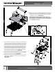
Operator's Manual LOCKDOWN 21 1-MAN Ladder Stand 26 34 5 4. Attach the right rear seat support (7) and the left rear seat support (6) to the underside of the rear platform (3) using four 5/16-18 x 2-1/4 IN bolts (30) and 5/16 IN locknuts (35). SEE FIGURE 3. FIGURE 3 7 NOTE: The seat mounting brackets need to be orientated so they are aligned to the outer edge of the corresponding rear seat support. 30 5.
Operator's Manual LOCKDOWN 21 1-MAN Ladder Stand 31 37 35 7 8. Attach the top of the right armrest (9) and the top of the left armrest (10) to the rear seat supports (6,7) using two 5/16-18 x 3-1/4 IN bolts (31), 5/16 IN washers (37) and 5/16 IN locknuts (35). Make sure that the seat posts are pointing inwards. SEE FIGURE 5. 9 FIGURE 5 6 NOTE: If the TearTuff™ backrest has slid over the holes, you may need to loosen the hardware of the backrest spreader to slide the backrest upwards.
Operator's Manual LOCKDOWN 21 1-MAN Ladder Stand 14. Attach the seat (11) to the seat mounting brackets of the rear seat supports (6,7) using two 1/4-20 X 2 IN bolts (27), four yellow M6 plastic washers (38), two yellow M6 plastic spacers (39) and two 1/4 IN flange locknuts (34). SEE FIGURE 7.
Operator's Manual LOCKDOWN 21 1-MAN Ladder Stand 25 17 18 18. Attach one shooting rail part A (17) to each end of shooting rail part B (18) using two 1/4-20 X 1-1/4 IN bolts (25) and 1/4 IN flange locknuts (34). SEE FIGURE 9. 34 19. Slide the ends of the shooting rail (17,18) onto the shooting rail pegs on the right and left armrests. SEE FIGURE 9. FIGURE FIGURE99 20.
Operator's Manual LOCKDOWN 21 1-MAN Ladder Stand 21 20 FIGURE 11 36 32 24. Attach stabilizer support tube (20) to the lowest middle ladder section (15) using 1/4-20 x 2 1/4 IN wing screw (33) and wing nut (36). SEE FIGURE 11. NOTE: Mounting hole is located just below top ladder rung on the middle ladder section. 25. Slide the bark biting stabilizer bar (21) into the stabilizer support tube (20) and secure using 1/4-20 x 1 3/4 IN wing screw (32) and wing nut (36).
Operator's Manual FIGURE 13A LOCKDOWN 21 1-MAN Ladder Stand 47 27. Attach the straps of the stabilizer bar ratchet assembly (47) to the stabilizer bar bark biting plate. 21 a. Feed the sewn loop of the long strap through either side slot in the bark biting plate and then feed the loose end through the sewn loop. SEE FIGURES 13A & 13B. c. Feed the sewn loop of the ratchet buckle strap through the opposite side slot in the bark biting plate and then feed the ratchet buckle through the sewn loop.
Operator's Manual LOCKDOWN 21 1-MAN Ladder Stand STOP READ AND UNDERSTAND THE FOLLOWING WARNINGS BEFORE SETUP AND USE WARNING WARNING Double check assembly steps to be certain you have correctly assembled this product. Study your new stand to become familiar with all of its features and design. At ground level, following provided use instructions, practice attaching stand to tree and removing stand from tree. Practice sitting, standing, and using this product before attaching overhead.
Operator's Manual LOCKDOWN 21 1-MAN Ladder Stand SETUP AND USE INSTRUCTIONS During installation and removal of ladder treestands, you must always and properly use the included Full Body Harness (Fall Arrest System). Refer to the Full Body Harness instructions included with this product for proper use. 1. Select a straight, healthy tree. Do Not attempt to install on a tree that is not healthy. 2.
Operator's Manual LOCKDOWN 21 1-MAN Ladder Stand 10. Locate the two ratchet portions with S-hooks for the criss cross straps (46). a. With one ratchet portion of the criss cross strap (46) now in hand, feed one long strap hanging down from platform through the center slot of ratcheting mechanism and back around through tightening lever. SEE FIGURES 17A & 17B. b.
Operator's Manual LOCKDOWN 21 1-MAN Ladder Stand FINISHED LADDER REMOVABLE VINYL DIPPED SHOOTING RAIL LARGE RATCHET STRAPS FOLD-AWAY VINYL DIPPED FOOTREST TEARTUFF™ MESH STORAGE SHELF LONG CRISS CROSS RATCHET STRAPS SILENT KNOB ASSEMBLIES STABILIZER BAR RATCHET STRAP OCTAGONAL LADDER TUBING BARK BITING STABILIZER BAR Check for parts online at www.HuntRiversEdge.
Operator's Manual LOCKDOWN 21 1-MAN Ladder Stand ILLUSTRATED PARTS BREAKDOWN 42 22 34 7 37 35 38 9 43 MESH HIDDEN FOR CLARITY 25 17 3 34 34 5 26 12 25 34 35 24 11 26 6 38 27 42 38 29 31 39 30 18 34 MESH HIDDEN FOR CLARITY 8 2 34 38 41 38 28 35 19 10 14 31 34 35 4 23 26 34 1 30 36 40 21 13 35 20 50 30 32 33 15 40 16 18 Check for parts online at www.HuntRiversEdge.
Operator's Manual LOCKDOWN 21 1-MAN Ladder Stand PARTS LIST ITEM # PART # DESCRIPTION QTY. ITEM # PART # DESCRIPTION 1 26825 2 J TUBES 2 24 26959 BOLT M6 X 1.
by WE ARE HUNTERS Rivers Edge® Treestands, Inc. Phone: 800-450-EDGE (3343) 1160 Eighth Avenue, PO Box 755 Fax: 715-822-2124 Cumberland, WI 54829 Email: info@huntriversedge.com *All weights, specifications and features are approximate and are subject to change without notice. Due to continuous product improvements, product images may not be exact. Warning labels in some product images may have been removed for photography purposes only. Props shown in photos not included.