Centauri® CONDENSING WATER BOILER INSTALLATION & MAINTENANCE MANUAL Models (1500, 1800, 2000) WB 250A-IFC Installation and service must be performed by a qualified service installer, service agency or the gas supplier. IMPORTANT: THIS MANUAL CONTAINS INFORMATION REQUIRED FOR INSTALLATION, OPERATION AND MAINTENANCE OF THIS EQUIPMENT. READ AND FOLLOW THE INFORMATION IN THIS MANUAL AND ALL OTHER PROVIDED INSTRUCTIONS, LABELS AND MARKINGS BEFORE INSTALLING, OPERATING OR SERVICING THIS UNIT.
TABLE OF CONTENTS 1. 2. 3. 4. 5. 6. 7. 8. Safety Considerations Standard Features and Equipment 2.1. Performance 2.2. Burner, Combustion Controls & Operating Controls 2.3. Remote/Network BAS Interface 2.4. Warranty and Service Policy Product Description Boiler Installation 4.1. Checking Equipment Before You Install 4.2. Codes 4.3. Electrical Requirements 4.4. Location 4.5. Service Clearances 4.6. Clearances to Combustible Surfaces General Piping Guidelines 5.1. Inlet and Outlet Connections 5.2.
9. 10. 11. 12. 13. 14. 15. 16. 17. Operating and Safety Controls 9.1. Operating Temperature Control 9.2. High Water Temperature Limit Control 9.3. Relief Valve 9.4. Electronic Low Water Cut-Off TempTrac Controller Panel 10.1. Principle of Operation 10.2. Upper LED Readout 10.3. Lower LED Readout 10.4. Control Buttons 10.5. Modulation Firing Sequence 10.6. To View the Setpoint 10.7. To Change The Setpoint 10.8. To Change Other Parameters 10.9. LED Display Alarm Messages Boiler Control Interface 11.1.
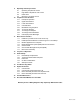
1. SAFETY CONSIDERATIONS WARNING: If the information in the supplied manual(s) is not followed exactly, a fire, explosion or exposure to hazardous materials may result, causing property damage, personal injury or loss of life. FOR YOUR SAFETY Do not store or use gasoline or other flammable vapors or liquids in the vicinity of this or any other appliance. WHAT TO DO IF YOU SMELL GAS Do not try to light any appliance. Do not touch any electric switch; do not use any phone in your building.
2. STANDARD FEATURES AND EQUIPMENT 2.1 2.2 2.3 2.
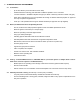
3 PRODUCT DESCRIPTION Component, Controls and Connection Locations (Locations May Vary) Model 2000 WB 250A-IFC 6 34-52 07/13
4 BOILER INSTALLATION 4.1 Checking Equipment Before You Install Inspect the unit completely upon receipt from the freight carrier before signing the bill of lading. Inspect the appliance and all accompanying parts for signs of impact or mishandling. Verify the total number of pieces shown on packing slips with those actually received. Contact the freight carrier immediately if any damage or shortage is detected. 4.
4.6 Clearances To Combustible Surfaces Minimum 1" clearance must be provided from any vent surface to adjacent combustible material. The minimum clearances to unprotected combustible material are 24" be provided at the front, 8" be provided at the rear and 8" at top, left and right sides of the appliance. 5 GENERAL PIPING GUIDELINES Consult factory for piping of hybrid boiler systems that contain both condensing and non-condensing boilers. 5.
1. 2. 3. 4. 5. Installing the boiler on a 4 inch to 6 inch housekeeping pad is recommended to ensure proper condensate drainage. Use 3/4” CPVC pipe to plumb each condensate drain separately to a suitable floor drain or collection system. Each condensate drain must contain a trap or siphon/pigtail to provide at least 3 inches of standing water, to prevent flue gas flow through the condensate piping.
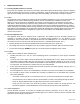
5.5 Temperature Control Sensor The Temperature Control Sensor is coiled and secured to the control enclosure along with the Sensor Thermal Well. Important: The thermal well must be installed in the return plumbing 1 to 4 feet from the return connection on the boiler. The sensor should then be inserted into the thermal well along with thermal conductive paste. Use the plastic threaded plug to secure the sensor in place. (See Illustration below.) 188 188 TEMPERATURE CONTROL SENSOR AND THERMAL WELL 5.
6.3 Gas Piping Size: Use the values in “Convert Fittings To Equivalent Straight Pipe” to add the equivalent straight pipe for each elbow or tee to obtain the total distance from the meter. Use this corrected total distance from the meter for determining the suggested pipe size in the “Single Unit Installation Suggested Gas Pipe Size” table.
6.4 Appliance Isolation during Gas Supply Piping Pressure Test 1. The appliance and its provided manual shutoff valve must be disconnected from the gas supply piping system during any pressure testing of that system at test pressures in excess of ½ PSI (3.5 kPa). 2. The appliance must be isolated from the gas supply piping system by closing its individual manual shutoff valve during any pressure testing of the gas supply piping system at test pressures equal to or less than ½ PSI (3.5 kPa). 3.
All Air From Inside The Building: Each opening requires a minimum free area of 1 square inch per 1000 Btu/hr input, but not less than 100 square inches (0.06 m2). Combination Of Air From The Indoors And From The Outdoors: Refer to National Fuel Gas Code, ANSI Z223.1 and/or CAN/CSA B149, Installation Codes or applicable provisions of the local building codes. NOTE: This unit may be installed with a remote air intake system which uses a make-up air duct to draw combustion air directly from outdoors.
7.3 Remote Combustion Air Cap A UL Listed air intake vent termination cap MUST be attached to the remote combustion air vent termination to adequately protect the combustion air inlet from wind and weather. A UL Listed air intake termination cap is available from Riverside Hydronics and may have shipped with the boiler as a purchased option. 7.4 Vertical or Horizontal Remote Air Duct Termination Air inlet and exhaust vents should terminate in the same wind pressure area whenever possible.
8.3 Maximum Category IV Vent Length (Equivalent Length) A vertical or horizontal remote Category IV vent system must be used with this appliance. The maximum length of field supplied Category IV vent is shown in the chart below titled Category IV Vent Equivalent Length. Maximum Category IV Vent Equivalent Length Vent Size Max Equivalent Length 6” Vent 7” Vent 8” Vent 9” Vent 100 feet 130 feet 250 feet 450 feet Pipe fittings reduce the maximum allowable vent length.
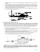
8.5 Combining Category IV Vents Combined Centauri or Centauri Plus Category IV gas vent systems must incorporate an Exhausto or Tjernlund variable speed, modulating, mechanical draft inducer capable of maintaining the appropriate negative draft at the end of the common flue, to assure that all boilers in the combined vent system operate with a negative draft. Do not exceed negative 0.25" W.C. See “Combining Vents with a Draft Inducer” illustration below.
9.4 Thermal Expansion A relief valve that discharges periodically may be due to thermal expansion in a closed system by components, such as a backflow preventer or check valve in the cold water supply or a closed boiler heating loop. These systems must be provided with means to control expansion. Contact a boiler or plumbing professional to resolve this situation. Do not plug the relief valve.
10 TEMPTRAC™ ELECTRONIC CONTROLLER PANEL 10.1 Principle Of Operation The boiler operates to satisfy the setpoint of the TempTrac digital control whose sensor is located in the return line of a Hydronic system. Demand (flow) will typically create a drop in temperature, thus activating the Centauri to add heat to the system. This setpoint is the highest temperature the appliance permits any firing to occur. 10.2 Upper Led Readout 10.
LABEL DEFAULT VALUE NET TEMPERATURE NET TEMP DETERMINED BY St1 165 165°F LED display value Hy1 -8 157°F St1 + Hy1 St4 -10 155°F St1 + St4 SR -10 145°F St1 + St4 + SR St1: The system’s desired maximum setpoint (when all firing ceases). This is the temperature setpoint of the appliance. The factory setpoint is 165°F. St1: The system’s desired maximum setpoint (when all firing ceases). This is the temperature setpoint of the appliance. The factory setpoint is 165°F.
10.6 10.7 C to D: Once modulation is established, the sensed loop temperature can fluctuate between 155°F and 145°F (between St4 and SR). The firing rate increases or decreases proportionately between 100% and low fire, depending upon the temperature sensed in the return loop. Temperature rise in the heat exchanger varies accordingly, 45° to 15° depending upon the firing rate. D: The unit will remain in modulation until the sensed temperature rises above 155°F (St4).
10.9 LED Display Alarm Messages Alarm messages are displayed in the upper LED readout and alternate with the default display. An alarm LED ICON is also illuminated.
11.3 BAS connection over network with MODBUS RTU protocol (requires option ALMMB) 11.4 An optional serial connection cable (part no. 106624) enables the TempTrac to communicate via Modbus RTU to a Building Automation System or to the OnTrac multiple boiler control. Connections are made using shielded, twisted pair wiring in a daisy chain arrangement.
Factory Default Settings - The values of the Outdoor Reset and Warm Weather Shutdown functions in the TempTrac control’s parameter Pr2 menu can be changed from the factory default values listed below: Display St1 tt rr2 rr1 tt2 Ht2 Parameter Description Temperature at the return boiler loop that activates /deactivates boiler firing Outdoor air temperature where outdoor reset is activated and deactivated Outdoor air temperature range through which St1 setting will be adjusted Maximum increase of St1 sett
12 SEQUENCE OF OPERATION 1. Incoming 120VAC a. Full time power to the Main Control Switch b. Full time power to the Variable Frequency Drive 2. Power On - When the main control switch is turned on: a. 120v is applied to the step-down transformer (24v) b. 120v is applied to the L.W.C.O. terminal L1 c. 120v is applied to the Fenwal Flame Safeguard Control d. 24v is applied to the TempTrac operating temperature control terminal L1 3.
8. Delay-On Relay - Once the Delay-On (Low Fire Hold) Relay has timed out, it energizes the Modulation Release Relay (SPDT) to enable the analog signal from the TempTrac to the VFD to regulate the speed of the blower. a. The TempTrac will continue to monitor the stored water temperature in the tank. b. When the setpoint temperature is reached the call-for-heat signal to the flame safeguard control is discontinued. c.
13 INITIAL STARTUP 13.1 Initial Startup Requirements Installation should be complete prior to performing initial startup; and the startup must be complete prior to placing the boiler into service. Starting the boiler without proper piping, combustion air, venting or electrical systems can be dangerous and may void the product warranty. The following startup instructions should be followed precisely in order to achieve safe and efficient operation to assure trouble-free service life.
c. 5. Reattach the manometer to the gas train manual shutoff valve at the burner and record the measured gas pressure in inches of water column (W.C.). Measure gas pressure again after 15 minutes. If gas pressure has increased 0.5" W.C. or more, the gas leak must be isolated to one or more of the operating gas valves. (For example, a solenoid actuated gas shutoff valve.
20. After the pre-purge, the flame control energizes the HSI for the heat up period, approximately 30 seconds. At the end of that period the gas valve is opened for approximately 4 seconds. After the burner has lit and the primary safety control senses a flame, the burner will remain on until the call for heat is satisfied or operation is interrupted by a safety device. 21. If the burner fails to light, the flame control will lockout.
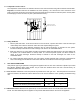
VALVE ORIFICE ADJUSTMENT MANIFOLD PRESSURE REGULATOR ADJUSTMENT INLET PRESSURE Gas Train Illustration REGULATOR ADJUSTMENT VALVE ORIFICE ADJUSTMENT LOW PRESSURE GAS SWITCH DUAL SAFETY SHUTOFF VALVE HIGH GAS PRESSURE SWITCH MANIFOLD PRESSURE Alternate Gas Train Illustration 29 34-52 07/13
14 TROUBLESHOOTING GUIDE Problem Probable Cause Corrective Action Power Supply Check fuse and/or circuit breaker. Check voltage at 120/24V step-down transformer. On-Off Switch Check if On-Off switch is lighted Check that the operating temperature control is set higher than the temperature of the boiler. Temperature Control Flame Safeguard Control Check for bad ground or bad control. Replace if necessary. Remote enable/disable open Enable boiler or place jumper between terminals R1-R2.
15 REPLACEMENT PARTS REPLACEMENT PARTS 31 34-52 07/13
15.
15.2 Control Panel Components (Optional components may not be included) Key No. Part No. 1 101947 2 Description Qty.
15.
15.4 Burner Assembly and Gas Train Components Optional components may not be included) Item 1 2 3 4 5 6 7 8 9 10 11 12 13 14 15 16 17 18 19 20 21 22 23 24 25 26 27 28 29 30 31 32 33 34 35 36 37 50 51 52 53 54 55 56 57 58 59 60 61 62 63 64 65 67 68 69 Qty Burner Assembly Components Part No. Description 1 1 1 1 1 1 1 1 1 4.30 2 1 4.
16 PERIODIC MAINTENANCE Listed below are items that must be checked to ensure safe reliable operations. Maintenance must be performed by a qualified service or maintenance provider. To ensure proper maintenance, the following instructions should be posted near the appliance and maintained in legible condition. Verify proper operation after servicing. Warning: When servicing the controls, use exact, Factory authorized, replacement parts and label all wires prior to disconnection.
6. The combustion air filter should be replaced every six months. If filter blockage becomes excessive the filter safety switch will not allow the burner to fire. To avoid nuisance shutdown in dirty environments, check and replace filter more frequently. See Filter Replacement Illustration below for removal detail. 7. Inspect low water cutoffs and relief valves for proper operation at every six months, or more often if indicated by inspection. 8.
17 RECOMMENDED MAINTENANCE SCHEDULE 1. 2. 3. 4. 5. Annual Maintenance a. Check all joints and pipe connections for tightness, corrosion or deterioration. b. Check the electronic-ignition system for quick ignition and a proper flame signal. c. Check all safety controls including thermostats for proper operation. d. Check safety shut-off valves for operation and tightness. e. Test flame failure detection system. f. Test high limit and operating temperature controls. g. Conduct a combustion test. h.
34-52 07/13
Riverside Hydronics, LLC 990 Haltom Road Ft. Worth, TX 76117 1‐800‐990‐5918 www.riversidehydronics.