
Troubleshooting guide


16
34-52 07/13
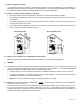
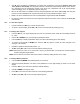
8.5 Combining Category IV Vents
Combined Centauri or Centauri Plus Category IV gas vent systems must incorporate an Exhausto or Tjernlund
variable speed, modulating, mechanical draft inducer capable of maintaining the appropriate negative draft at the end
of the common flue, to assure that all boilers in the combined vent system operate with a negative draft. Do not
exceed negative 0.25" W.C. See “Combining Vents with a Draft Inducer” illustration below.
WARNING: Do not connect multiple boiler vents into a single unpowered or fixed speed powered vent. This
could cause unsafe operation and the potential for poisonous carbon monoxide to enter occupied areas.
Such improper installation can cause property damage, personal injury, exposure to hazardous materials or
loss of life.
Conventional Venting Through the Wall Venting Combining Vents with a Draft Inducer
9 OPERATING AND SAFETY CONTROLS
9.1 Operating Temperature Control
An adjustable digital operating control is located in the front control panel. See TempTrac Electronic Controller Panel
in this manual for more information.
9.2 High Water Temperature Limit Control
The boiler is equipped with adjustable limit and high limit controls to control the maximum discharge water
temperature. These controls are located inside the control cabinet and are accessed by removing the bottom cover.
The High Limit Control is of the manual reset type and may be reset by pressing the limit reset button accessible
through the control panel cover. The Lower Limit is of the auto reset type and can be dial adjusted to operate just
above the set point of the main Operating Temperature Control. Pressing the reset on the High Limit Control will not
cause the control to reset until the water temperature has dropped below the set point of the manual reset High Limit
Control.
Warning: Turn off all electrical service to the appliance when accessing the limit or high limit controls
located inside the control cabinet. This cabinet contains High Voltage wiring and terminals. If the electrical
service is not turned off and these terminals are touched, a dangerous shock causing personal injury or loss
of life could occur. Close and fasten the control cabinet cover before restoring electrical service to the
appliance.
9.3 Relief Valve
A pressure only relief valve(s) sized in accordance with the ASME Boiler and Pressure Vessel Code, Section IV, is
installed in the tank.
Caution: Do not install a reducing coupling, valve or other restriction in the relief valve(s) discharge line. The
discharge line shall allow complete drainage of the valve and line. Relief valves should be manually operated at least
once a year.
Warning: To prevent burns caused by hot water discharge and water damage, pipe the discharge from the
relief valve to a suitable floor drain for disposal when relief occurs. Avoid contact with hot discharge water.