
Troubleshooting guide


22
34-52 07/13
11.3 BAS connection over network with MODBUS RTU protocol (requires option ALMMB)
An optional serial connection cable (part no. 106624) enables the TempTrac to communicate via Modbus
RTU to a Building Automation System or to the OnTrac multiple boiler control. Connections are made using
shielded, twisted pair wiring in a daisy chain arrangement.
11.4 Making BMS/BAS remote connections for analog and binary (on/off) signals
A terminal strip for the remote connection is located behind the hinged control panel at the top of the cabinet and
is accessed by removing the bottom cover and then removing the screws at the top of the hinged cover.
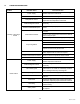
Important: Do not use single strand bell wire for remote field connections to terminals R1-R2 and C1-C2. Use only
multi-strand copper wire. See table below for wire length and gauge:
Warning: Turn off all electrical service to the appliance when accessing the remote connections located
inside the control cabinet. These terminals are High Voltage. If the electrical service is not turned off and
these terminals are touched, a dangerous shock causing personal injury or loss of life could occur. Close
and fasten the control cabinet cover before restoring electrical service to the appliance
The Following Describes The Functions Of Each Of These Terminals And The Factory-Installed Options
Required To Activate The Terminals:
Note: Terminals A1-A2 and P1-P2 are functional only when the boiler is equipped with the factory installed options
required to activate the terminals. Terminals R1-R2, C1-C2 and T1-T2 are standard pre-wired functions on all
models.
R1-R2: Used to activate /de-activate boiler from remote master control.
Terminals are wired to a relay in a remote Boiler Management or Energy Management System. When relay
closes, circuit from R1 to R2 is completed and appliance controls are enabled. Appliance ships from factory with
jumper between terminals Remove jumper when connecting to a remote controller.
A1-A2: Used to activate a remote alarm signaling shutdown of combustion control.
Provides a maximum 10 amp relay contact closure when the flame safeguard terminates combustion due to a
tripped safety interlock (i.e.: air proving switch high limit switch, low water flow switch or flame sensor, etc.).
Options Required - Consult Factory
P1-P2: Activates remote equipment and requires confirmation signal back to the appliance.
Provides a maximum 10-amp relay contact closure to activate a remote device (i.e.: mechanical room air louvers,
draft inducer or power vent, etc.). The remote device must send return signal via proving switch to confirming
proper operation to terminals C1-C2, prior to the appliance being able to energize. Options Required - Consult
Factory
C1-C2: Used for proving operation of remote device.
Terminals are wired to a proving switch on a remote device such as a power venter. When relay closes, circuit
from C1 to C2 is completed and appliance controls are enabled. This appliance ships form the factory with jumper
between terminals.
T1-T2: Used for external modulation control
To connect external modulation control, disconnect and cap the blue wire connected to terminal T2 and connect
the external modulating signal to terminals T1 (positive) and T2 (negative).
11.5 Outdoor Reset (requires option for outdoor reset through the TempTrac control, code OUTRC)
The TempTrac control is capable of an outdoor reset function independent of an external control. The option
includes a third sensing probe and activates the probe in the TempTrac. The outdoor reset function overrides the
St1 setting when the outdoor air temperature falls to the tt setting. St1 is increased in increments through the
range established by rr2. When the outdoor air temperature falls to the bottom of the rr2 range, the St1 setting will
have been adjusted upward by the amount of the rr1 value. (See Outdoor Reset Manual #34-400.6 for full
description.)
Wire Gauge 18 GA 16GA 14 GA 12 GA
Maximum Length 30 FT 50 FT 75 FT 100 FT