
- Riverstone Switch Router Getting Started Guide


Riverstone Networks RS 2100 Switch Router Getting Started Guide 3-5
Hardware Installation Hardware Specifications
Connecting a 10/100BASE-TX Management Cable
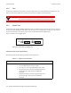
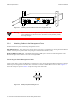
Use the RJ-45 10/100BASE-TX DTE port for connecting the RS 2100 to your network for in-band management
through either Telnet or SNMP. Figure 3-3 shows the pin positions of the 10/100BASE-TX port, and Table 3-3 shows
the wiring map for the MDI management cable:
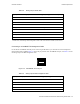
Figure 3-3 10/100BASE-TX RJ-45 port
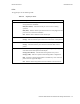
Table 3-2 Wiring map for serial cable
Signal (RS 2100 serial port) Pin Signal (management console port)
Unused 1 Unused
TXD (transmit data) 2 RXD (receive data)
a
RXD (receive data) 3 TXD (transmit data)
Unused 4 Unused
GND (ground) 5 GND (ground)
Unused 6 Unused
CTS (clear to send) 7 CTS (clear to send)
RTS (request to send) 8 RTS (request to send)
Unused 9 Unused
a. The left hand column pin assignments are for the male DB-9 connector on the RS 2100. Pin 2 (TXD or
“transmit data”) must emerge on the management console’s end of the connection as RXD (“receive data”).
Table 3-3 Wiring map for MDI management cable
Signal (RS 2100 port) Pin Signal (management console port)
TXD (transmit data) 1 RXD (receive data)
a
TXD (transmit data) 2 RXD (receive data)
RXD (receive data) 3 TXD (transmit data)
Unused 4 Unused
Unused 5 Unused
87654321