Switch Gizmo User’s Manual RJM Music Technology, Inc.
Switch Gizmo User’s Manual Version 1.0 June 27, 2013 RJM Music Technology, Inc. 2525 Pioneer Ave #1 Vista, CA 92081 E-mail: support@rjmmusic.com Web: www.rjmmusic.
Copyright © 2013 RJM Music Technology, Inc. All Rights Reserved. Amp Gizmo, MasterMind, Mini Amp Gizmo, Switch Gizmo and the RJM logo are trademarks of RJM Music Technology, Inc. All other trademarks are the property of their respective owners.
Table of Contents INTRODUCTION 1 FRONT PANEL 2 BACK PANEL 3 MIDI USAGE 5 Continuous Controllers 6 Bank Selection 6 Backing Up Your Settings: SysEx Dump 7 CONTROLLING MULTIPLE DEVICES 8 SETUP MODE 9 9 Selecting MIDI Channel 9 MIDI Channels Saving MIDI Channel 10 Selecting MIDI Options 10 Continuous Controller Ranges 10 GCX Compatibility Mode 10 Bank Select Enable 10 Saving MIDI Options 11 Invert Mode 11
Introduction Thank you for purchasing a Switch Gizmo. This product is designed to connect to your amplifier, effects devices or other electronic equipment and give them MIDI switching capabilities. This allows you to integrate then into a MIDI based guitar rig.
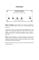
Front Panel Switch Gizmo MIDI Controlled Function Switcher 1 2 3 4 Write RJM Music Technology, Inc. Buttons 1 through 4 - These buttons turn switches 1 through 4 on and off. The button lights up when the corresponding function switch is on. These function switches will control all footswitchable features of an amplifier or other device connected to the Switch Gizmo.
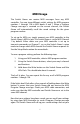
Back Panel 1/2 and 3/4 – These jacks connect to the footswitch or external switching jacks of your amplifier or other device. The tip conductor of the 1/2 jack is controlled by the 1 button on the front panel, and the ring conductor is controlled by the 2 button. Likewise, the tip of the 3/4 jack is controlled by the 3 button and the ring is controlled by the 4 button. When a switch on the front panel is active, the tip or ring of the corresponding jack is shorted to the jack’s sleeve (ground).
draw 350mA or less. Moving to a higher capacity power supply will allow you to phantom power MIDI controllers with higher current requirements – just add the current requirement of the device with the Switch Gizmo’s requirement (150mA) and make sure your adapter can supply at least that amount of current. Power – This unit requires power supply in the range of 9 to 12 volts, AC or DC. The plug should be a 5.5mm/2.1mm barrel connector, similar to those used in most effects pedals.
MIDI Usage The Switch Gizmo can receive MIDI messages from any MIDI controller. You can store different switch settings for MIDI program numbers 1 through 128 in MIDI banks 0 and 1. When a Program Change message is received on the correct channel, the Switch Gizmo will automatically recall the saved settings for the given program number. To set up for MIDI use, simply connect your MIDI controller to the Switch Gizmo’s MIDI In jack. The Switch Gizmo is set for MIDI Channel 1 by default.
amp’s channel and functions whenever it receives a MIDI Program Change message. Continuous Controllers In addition to supporting MIDI Program Change messages, the Switch Gizmo supports MIDI Continuous Controller messages.
to select the current MIDI bank. Bank numbers above bank 1 are ignored. Bank selection is disabled by default. See the Setup Mode section for information on how to enable bank selection. Backing Up Your Settings: SysEx Dump A SysEx (System Exclusive) data dump will send the current Switch Gizmo system configuration out through the MIDI Thru/Out port. You can then save this data to your computer, or copy the settings directly to another Switch Gizmo.
Controlling Multiple Devices The Switch Gizmo features two electrically isolated switching jacks, which makes it safe to connect each jack to a different device. When connected this way, the 1 and 2 buttons control the first device and the 3 and 4 buttons control the second device. Even though it is possible to split the 1/2 or 3/4 jacks into two mono ¼-inch plugs using an insert cable and connect those plugs to two different devices, this is not a recommended configuration.
Setup Mode To configure the Switch Gizmo, you must first enter setup mode. Holding down selected buttons while powering the unit on will bring up selected setup modes, as detailed in this section. Selecting MIDI Channel Hold the 1 button while powering the Switch Gizmo on. Keep holding the button until the LEDs flash. The Switch buttons will now allow you to select the MIDI channel the Switch Gizmo responds to. MIDI Channels The Switch Gizmo is set by default to send and receive on MIDI Channel 1.
Saving MIDI Channel Once you’ve set the MIDI channel, press the Write button. The Switch Gizmo is now in normal operational mode. Selecting MIDI Options A separate mode will allow you to select MIDI continuous controller numbers and other options. Hold the 4 button while powering the Switch Gizmo on. Keep holding until the LEDS flash.
MIDI bank select messages. When button 4 is on, the Switch Gizmo will respond to Bank Select messages as described in the Bank Selection section. Saving MIDI Options Once you’ve set the desired MIDI options, press the Write button. The Switch Gizmo is now in normal operational mode. Invert Mode Some amplifiers may have inverted polarity on some functions. This can cause the Switch Gizmo to display a function as off when the function is actually on, and as on when the function is actually off.
then re-opening them. In momentary mode, the Switch Gizmo switches will close for 100 milliseconds before opening again.) To enter momentary mode, hold down the 3 button while powering up the Switch Gizmo. Keep holding the button until the LEDs flash. Use the front panel buttons to light the LED of any function that needs to be momentary. Make certain that no other LED is lit. Once you’ve selected the buttons for the momentary functions, press the Write button.
Troubleshooting Problem: The LEDs don’t flash when you hold down the Write Button. Solution: The Switch Gizmo did not receive a MIDI Program Change message. First, verify that you have a valid MIDI connection. The MIDI output of your MIDI controller should be connected to the MIDI input of the Switch Gizmo by a MIDI cable that’s known to be working correctly. The next most likely cause is that the Switch Gizmo is set to a different MIDI channel than your MIDI controller.
Specifications Dimensions Weight Power Phantom Power Memory Quarter-rack enclosure 4 (W) x 1.5 (H) x 4 (D) inches 10.2 (W) x 3.8 (H) x 10.2 (D) cm 10.3 ounces 300 grams 9 to 12 Volts, AC or DC @ 150mA 5.5mm OD, 2.1mm ID x 9.5mm barrel connector Provided over pins 6 and 7 of the MIDI In jack. Phantom power voltage is the same as the power provided at the Power jack.