
Instruction manual

7. COMMUNICATION DATA LIST
IMR01Y06-E6
71
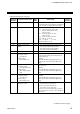
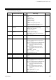
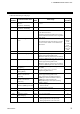
Continued from the previous page.
Extension
number
Communication item
Attri-
bute
Data range
Factory
set value
221
Heater break alarm 1
(HBA1) type
R/W
0: Heater break alarm 1 (HBA1) type A
(Time-proportional control output)
1: Heater break alarm 1 (HBA1) type B
(Continuous control output)
Time-proportional control output:
Relay, Voltage pulse, Triac, or Open
collector output
Continuous control output:
Voltage/Current continuous output
Based on
OUT1 of
FB100/400/
900 model
code.
Time-
proportional
control output:
0
Continuous
control output:
1
222
Number of heater break
alarm 1 (HBA1) delay times
R/W
0 to 255 times
5
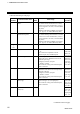
223
CT1 assignment
R/W
0: None
1: OUT1
2: OUT2
3 to 6: Do not set this one
1
224
CT2 ratio
R/W
0 to 9999
When not
specifying:
800
CTL-6-P-N:
800
CTL-12-S56
-10L-N:
1000
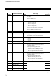
225
Heater break alarm 2
(HBA2) type
R/W
0: Heater break alarm 2 (HBA2) type A
(Time-proportional control output)
1: Heater break alarm 2 (HBA2) type B
(Continuous control output)
0
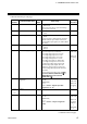
226
Number of heater break
alarm 2 (HBA2) delay times
R/W
0 to 255 times
5
227
CT2 assignment
R/W
0: None
1: OUT1
2: OUT2
3 to 6: Do not set this one
1
228 Unused
⎯ ⎯ ⎯
229 Unused
⎯ ⎯ ⎯
230
Hot/Cold start
R/W
0: Hot start 1
1: Hot start 2
2: Cold start
3: Stop start
0
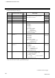
231
External input type
R/W
0: Remote setting input (Remote control)
1: Intercontroller communication Cascade
control
2: Intercontroller communication Ratio setting
When performing Cascade control or Ratio
setting, set the master controller to 0 (Remote
control). Set slave controllers to 1 (Cascade
control) or 2 (Ratio setting).
0
Continued on the next page.