01 Series Operator’s Manual Part Number: 71-0093RK Revision: A Released: 2/2/11 www.rkiinstruments.
WARNING Read and understand this instruction manual before operating instrument. Improper use of the gas monitor could result in bodily harm or death. Periodic calibration and maintenance of the gas monitor is essential for proper operation and correct readings. Please calibrate and maintain this instrument regularly! Frequency of calibration depends upon the type of use you have and the sensor types.
Warranty RKI Instruments, Inc. warrants the 01 Series Single Gas Monitor sold by us to be free from defects in materials, workmanship, and performance for a period of two (2) years from the date of shipment from RKI Instruments, Inc. This includes the instrument and the original sensor. Replacement parts are warranted for one (1) year from the date of their shipment from RKI Instruments, Inc. Any parts found defective within their warranty period will be repaired or replaced, at our option, free of charge.
Table of Contents Introduction . . . . . . . . . . . . . . . . . . . . . . . . . . . . . . . . . . . . . . . . . . . . . . . . . . . . . . . . . . 1 Specifications. . . . . . . . . . . . . . . . . . . . . . . . . . . . . . . . . . . . . . . . . . . . . . . . . . . . . . . . . 2 Description . . . . . . . . . . . . . . . . . . . . . . . . . . . . . . . . . . . . . . . . . . . . . . . . . . . . . . . . . . . 4 Protective Rubber Boots . . . . . . . . . . . . . . . . . . . . . . . . . . . . . . . . . . . . . . .
Maintenance . . . . . . . . . . . . . . . . . . . . . . . . . . . . . . . . . . . . . . . . . . . . . . . . . . . . . . . . . 22 Troubleshooting . . . . . . . . . . . . . . . . . . . . . . . . . . . . . . . . . . . . . . . . . . . . . . . . . 22 Replacing the Batteries . . . . . . . . . . . . . . . . . . . . . . . . . . . . . . . . . . . . . . . . . . . . 23 Replacing the Sensor . . . . . . . . . . . . . . . . . . . . . . . . . . . . . . . . . . . . . . . . . . . . .
Introduction Using an advanced microprocessor controlled detection system, the 01 Series Personal Single Gas Monitor detects the presence of either carbon monoxide (CO), hydrogen sulfide (H2S), or oxygen (O2). The 01 Series’s compact size and easy-to-use design makes it ideally suited for a wide range of applications, including sewage treatment plants, tunnels, hazardous waste sites, petrochemical facilities, oil fields, mines, and chemical plants.
Specifications Table 1: 01 Series Specifications CO-01 HS-01/HS-01S OX-01 Carbon Monoxide (CO) Hydrogen Sulfide (H2S) Oxygen (O2) Detection Range 0 to 500 ppm 0 to 100.0 ppm 0 to 40.0% vol. Display Increment 1 ppm 0.5 ppm 0.1% vol. Detection Principle Electro Chemical Electro Chemical Galvanic Cell Alarm Points Low High TWA STEL Target Gas Sampling Method 25 ppm 50 ppm 25 ppm 200 ppm Low High TWA STEL 10.0 ppm 30.0 ppm 10.0 ppm 15.0 ppm Low 19.5% vol. (decreasing) High 23.5% vol.
Table 1: 01 Series Specifications CO-01 Optional Accessories Dimensions and Weight Operating Temp. & Humidity 3 • Specifications • • • • HS-01/HS-01S OX-01 Calibration Adapter Calibration Kit Alligator Clip Belt Clip 1.4” (35mm) W x 4.1” (104mm) H x 0.8” (20mm) D; 3.5 oz.
Description This section describes the components of the 01 Series. These components include the 01 Series’ protective rubber boots, case, membrane retainer and filter disks, sensor retainer, sensor, LCD, control buttons, printed circuit boards, alarm lights, buzzer, vibrator, and batteries.
Protective Rubber Boots A protective rubber boot is installed over each end of the 01 Series. The sensor end boot fits over the sensor cover end of the 01 Series and the battery end boot fits over the battery cover end of the 01 Series. Case The 01 Series’ sturdy, high-impact plastic case is blue in color. The case is suitable for use in many environmental conditions, indoors and out. The unit is dust proof and weather resistant.
Alligator and Belt Clips The 01 Series is available with two types of clips, the alligator clip and the belt clip. Both are illustrated in Figure 2 below. Belt Clip Alligator Clip Figure 2: Alligator & Belt Clips The alligator clip can be used to attach the 01 Series to clothing or a belt. Teeth in the clip’s jaws prevent the unit from slipping off. The belt clip is used to easily clip the 01 Series on a belt.
noticed, especially in the presence of H2S, change the charcoal filter disk (see the Maintenance section for instructions). Sensor Retainer The sensor retainer holds the sensor in place. It is attached to the top of the case by two Phillips screws. The sensor retainer also covers the buzzer. Should the sensor require replacement, refer to the Maintenance section for sensor replacement instructions. The buzzer, however, is not field replaceable.
When either of the two control buttons are pressed, the LCD backlight comes on for 20 seconds. Control Buttons Below the LCD are two control buttons: POWER/MODE and AIR. The POWER/MODE button turns the 01 Series on and off. The functions performed by the control buttons are summarized in the following table: Table 2: 01 Series Control Buttons Button Function POWER/MODE • Turns the unit on and off. • Turns the LCD back light on. • Displays STEL and TWA readings (HS-01 & CO01).
Alarm Lights The 01 Series has two red LED alarm lights. They alert you to gas, low battery, and sensor failure alarms. The smaller of the two lights is square, has a frosted plastic cover, and is located at the top of the unit to the left of the membrane retainer. The larger alarm light is rectangular in shape, has a diamond-grid pattern etched into the plastic cover, and is located to the left of the LCD on the front of the case. Buzzer A solid-state electronic buzzer is mounted inside the 01 Series.
Start Up This section explains how to start up the 01 Series and to get it ready for operation. Start-up Procedure 1. Press and hold the POWER/MODE button for three seconds to turn on the 01 Series. For several seconds, all elements of the LCD display and the LCD backlight turn on. The vibrator activates briefly, and it then shuts off. The alarm lights flash on and the buzzer sounds, and then they both turn off. 2.
Operation This section describes the normal operation of the 01 Series in Measuring Mode. It explains how the unit can be used to display peak, STEL, and TWA readings for the HS-01 and CO-01, and minimum and maximum readings for the OX-01. It also covers alarm indications. Measuring Mode To put the 01 Series in Measuring Mode, assuming the unit is off, press and hold the POWER/MODE button for three seconds. Before continuing, it is advisable to perform a fresh-air adjustment in a fresh-air environment.
1. The unit must be in Measuring Mode. The current gas concentration should be displayed on the LCD. 2. Press and release the POWER/MODE button to enter Peak Gas Display Mode. The LCD backlight will activate and the LCD will display the peak gas reading. A small peak symbol is displayed in the upper left corner of the LCD. 3. Press and release the POWER/MODE button again to enter STEL Display Mode. This will display the STEL reading. The word “STEL” is displayed in the middle of the LCD above the reading.
Alarms This section covers alarm indications. It also tells you how to reset the 01 Series after an alarm has occurred and how to respond to an alarm condition. Alarm Indications The 01 Series will sound an alarm, flash its alarm lights, and vibrate when the target gas concentration rises above the low alarm point. The 01 Series also sounds an alarm, flashes its alarm lights, and vibrates when the high alarm point is reached.
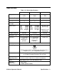
Table 3: Alarm Types and Indications Alarm Type LCD Indications Other Indications Over Range Concentration of gas rises above the measuring limit of the 01 Series. (Or there could be a problem with the unit.) • Gas reading replaced by blinking brackets. • Pulsing tone occurs once per second. • Unit vibrates once per second. • Alarm light flashes. Low Battery Warning • Last remaining bar on the right in battery icon flashes. • None Dead Battery Alarm • Gas reading replaced by FAIL.
Responding to Alarms This section describes response to gas, over range, battery, sensor failure, and system failure alarms. Responding to Gas Alarms 1. Follow your established procedure for an increasing gas condition or a decreasing oxygen condition. 2. Reset the alarm by pressing and releasing the POWER/MODE button after the alarm condition has been cleared. Responding to an Over Range Alarm WARNING: An over range condition may indicate an extreme toxic gas or oxygen concentration.
possible. Refer to the instructions in “Replacing the Batteries” for more information. Responding to a Sensor Failure Alarm 1. Try calibrating the 01 Series first, as described in “Calibration”, before replacing the sensor. 2. If the sensor failure continues, replace the sensor as described in “Replacing the Sensor”. 3. If the gas sensor failure condition continues after you have replaced the gas sensor, contact RKI Instruments, Inc. for further instructions. Responding to a System Failure Alarm 1.
3. As soon as segments appear on the display (approximately one second), release the AIR button. When the unit “beeps,” release the POWER/MODE button to put the 01 Series into Alarm Point Adjustment Mode. The LCD should display the low alarm setting and the battery level. Rising Alarm . Battery level 10.0 Alarm point ppm Alarm LO Name Figure 4: LCD in Alarm Adjustment Mode, CO-01 & HS-01 Falling Alarm Alarm Name Battery level . 19.
NOTE: If you press and hold the POWER/MODE button for too long (about five seconds), you will turn off the unit. 6. Use the AIR button to change the high alarm point setting. Pressing and releasing the AIR button in quick succession increases the high alarm point one number at a time. Pressing and holding the AIR button increases the high alarm point at a faster rate.
Calibration This section covers the calibration of the 01 Series. Setting the fresh air reading is described first followed by setting the span (CO-01 and HS-01) or zero (OX-01) reading. You are also told what is needed to complete the task and how to assemble the calibration kit. WARNING: Use a 0.5 LPM (liters per minute) fixed flow regulator when calibrating. Using a different flow rate may adversely affect the accuracy of the calibration.
NOTE: On the OX-01, instead of 100% nitrogen (0% oxygen), it is allowable to use higher than 0% oxygen to set the zero level. RKI Instruments, Inc. recommends 18% oxygen or lower. • To carry out the calibration, you will need a fixed-flow regulator with a flow rate of 0.5 LPM (liters per minute), non-absorbent tubing, and the calibration adapter that will fit over the 01 Series’ sensor. Assembling the Calibration Kit WARNING: Calibrate the 01 Series in a non-hazardous environment. 1.
NOTE: If one of the control buttons is not pressed within 10 minutes, the unit will return to Measuring Mode automatically. 6. Attach the regulator to the gas cylinder. The fixed-flow regulator automatically begins introducing the calibration sample to the sensor. 7. Let the gas flow for two minutes. After two minutes, press the POWER/ MODE button. The unit will adjust the span (CO-01 and HS-01) or zero (OX-01) based on the calibration value that was saved in step 5 above.
Maintenance This section describes troubleshooting procedures for the 01 Series. It also describes how to change the 01 Series’s batteries as well as how to replace the sensor and sensor cover. WARNING: RKI Instruments, Inc. recommends that service, calibration, and repair of RKI instruments be performed by personnel properly trained for this work. Replacing sensors and other parts with original equipment does not affect the intrinsic safety of the instrument.
Table 5: Troubleshooting the 01 Series Probable Causes Symptoms Recommended Action • “FAIL” displays during span adjustment. • The calibration value may not match the cylinder gas concentration. • The sample gas is not reaching the sensor because of a bad connection. • The calibration cylinder may be out of gas or is outdated. • The sensor may need replacement. 1. Check all calibration tubing for leaks or for any bad connections. 2. Make sure the 01 Series has been properly set up for calibration. 3.
POWER MODE CO-01 CO AIR 3. Rotate the captive battery cover screw counterclockwise to remove battery compartment door. Figure 6: Removing the Battery Compartment Door 4. Carefully remove the old alkaline batteries. 5. Carefully install the new AAA alkaline batteries. Follow the battery diagram inside the battery compartment. 6. Reinstall the battery cover.
4. Carefully remove the old sensor from the sensor socket. 5. Carefully insert the replacement sensor in the socket. Make sure the sensor face with the colored ring is facing up. Allign slots in CO & H2S sensors with tabs in case. Tab Tab Note: Oxygen sensor is not keyed. Unit shown without Sensor Retainer Figure 8: Replacing the Sensor CAUTION: When replacing the sensor, verify that the sensor is properly aligned with its socket before inserting it into the socket.
Figure 9: Replacing the Sensor Filters 3. Rotate the membrane retainer about one-quarter turn counterclockwise to remove it from the sensor retainer (the top of the unit). 4. Carefully remove the sensor cover from the recess in the senor retainer. If you have a CO-01, also remove the charcoal filter. 5. If you have a CO-01, install a charcoal filter into the smaller recess and make sure they are properly seated in the recess.
Parts List Table 6lists replacement parts and accessories for the 01 Series. Table 6: Parts List Part Number Description 06-1248RK Calibration kit tubing (specify length in feet) 07-6009RK Gasket for battery cover 10-1099RK Screw, M2X 4mm pan head Phillips, stainless steel, for membrane retainer 10-1105RK Screw, M2X 8mm pan head Phillips, stainless steel, for sensor retainer 10-1141RK Screw,M2.5 x 3mm pan head Phillips, stainless steel, for alligator and belt clip installation.
Table 6: Parts List Part Number Description 81-1004RK Regulator, fixed flow, 0.