30-0951RK-01, 30-0951RK-HS-01, 30-0951RK-OC-01, and 30-0951RK-IR-01 Flow Through Adapters Part Number: 71-0281RK Revision: P1 Released: 6/3/13 www.rkiinstruments.
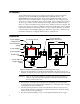
Description The attached detector head operator’s manual can be used in conjunction with this supplement for the 30-0951RK-01, 30-0951RK-HS-01, 30-0951RK-OC-01, or the 30-0951RK-IR-01 flow through adapter. The flow through adapter includes a sensor adapter and a sensor chamber with two compression fittings. A sensor adapter gasket seals to the 1/2” NPT combustible sensor when installed. A sensor adapter O-ring seals to all other types of detectors when installed.
aluminum, or stainless steel. The inlet fitting is located on the side of the sensor chamber and the exhaust fitting is located on the bottom. Insert the desired length of tubing into each fitting and tighten the fittings so that the ferrules crimp onto the tubing. 5. Install appropriate device(s) (pump, aspirator, etc.) to draw sample to the detector.
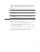
Parts List See the table below for spare parts not listed in the attached detector manual. Table 1: Parts List Part Number 3 Description 07-0107RK Gasket, 0.75 OD x 0.58 ID x 0.093 thick, for 1/2” NPT combustible sensor adapter 07-7120RK O-ring, 0.987 ID x .103, buna, for O2/CO sensor adapter 07-7218RK O-ring, 0.734 x .139, buna, for IR and H2S sensor adapters 07-7225RK O-ring, 1.243 ID x .139, buna, for sensor chamber 13-1070RK Captive panel screw, 10-32 x 1.