30-0951RK-O2/CO Sample Draw Aspirator Adapter Operator’s Manual Part Number: 71-0019RK Revision: A Released: 6/2/10 www.rkiinstruments.
Product Warranty RKI Instruments, Inc. warrants gas alarm equipment sold by us to be free from defects in materials, workmanship, and performance for a period of one year from the date of shipment from RKI Instruments, Inc. Any parts found defective within that period will be repaired or replaced, at our option, free of charge. Parts must be returned to RKI Instruments, Inc. for repair or replacement.
Overview This manual describes the 30-0951RK-O2/CO sample draw aspirator adapter. It also describes how to install and use the adapter. A spare parts list at the end of this manual lists replacement parts. Specifications Table 1 lists specifications for the Sample Draw Aspirator Adapter. Table 1: Specifications Applicable Detectors • 65-2511RK, Oxygen detector (see note below) • 65-2433RK-05, CO detector • Consult RKI Instruments, Inc.
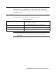
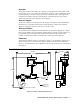
Description The sample draw aspirator adapter uses compressed air flowing through a venturi to draw air into a sample chamber. The sample draw adapter screws directly onto the gas detector. Adapter Gasket (in bottom of adapter) Screw Onto Combustible Sensor Sensor Adapter Flowmeter Sensor Chamber Chamber O-ring (in top of chamber) Pressure Regulator 1/4 O.D. Tube Compressed Air Inlet Fitting Thumbscrew (3X) Aspirator - + 1/4 O.D.
Aspirator The aspirator inlet is connected to the output port on the right side of the regulator and the vacuum port on top is connected to the detector chamber. It has a venturi tube inside it which generates a vacuum at its top port when compressed air flows through it. The compressed air and the air drawn from the detector chamber into the top port of the aspirator both exhaust at the right side of the aspirator. Detector Adapter The detector adapter screws directly onto the Oxygen/CO detector.
1. Install and startup the detector head as described in the detector head operator’s manual. Make sure there is sufficient room between the detector and the mounting surface to install the sample draw adapter. 2. The sample draw adapter is normally shipped installed to the detector. If not, screw the detector adapter onto the detector tightening firmly by hand and then attach the chamber (with the regulator, aspirator and flowmeter attached) onto the detector adapter with the three captive thumbscrews.
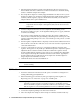
calibration adjustments necessary. 5. Disconnect the sample bag from the flowmeter inlet. Parts List Table 2 lists replacement parts and accessories for the sample draw adapter. Table 2: Parts List Part Number Description 06-1248RK Tubing, 3/16 x 5/16, polyurethane, for calibration kit 07-7120RK O-ring, 0.987 ID x .103, buna, for detector adapter 07-7225RK O-ring, 1.243 ID x .139, buna, for detector chamber 13-1070RK Captive panel screw, 10-32 x 1.