
Manual

30-0951RK-O2/CO Sample Draw Aspirator Adapter • 5
Aspirator
The aspirator inlet is connected to the output port on the right side of the regulator and
the vacuum port on top is connected to the detector chamber. It has a venturi tube inside
it which generates a vacuum at its top port when compressed air flows through it. The
compressed air and the air drawn from the detector chamber into the top port of the
aspirator both exhaust at the right side of the aspirator.
Detector Adapter
The detector adapter screws directly onto the Oxygen/CO detector. It is installed hand
tight. It has an o-ring inside it which seals against the detector. When removing this
adapter to change the detector, be sure not to lose this o-ring.
Detector Chamber
The chamber has three thumbscrews which fasten it to the detector adapter. An o-ring at
the top of the chamber seals the chamber/adapter interface. The inlet of the chamber is on
the right side and is connected to the exhaust of the flowmeter. The exhaust of the
chamber is at the bottom and is connected to the vacuum port of the aspirator.
Flowmeter
The flowmeter indicates the flow to the detector. It has a 1/4” tube fitting at its inlet port
and its exhaust port is connected to the detector chamber. The flowmeter’s indication
range is 1 - 10 SCFH. It has no flow adjustment valve because the flowrate is controlled by
the regulator.
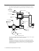
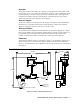
Installation
Figure 2: Outline & Mounting Dimensions
1.25
Aspirator/Sample
Exhaust
(1/8 NPT female)
Screw Onto Combustible Sensor
1/4 O.D. Tube Sample
Inlet Fitting
4.00 max
-
+
1/4 O.D. Tube Compressed Air Inlet
Fitting
9.50 max
8.20 max