35-3000RK-LEL/O Sample-Draw Detector Operator’s Manual Part Number: 71-0223RK Revision: P1 Released: 2/28/11 www.rkiinstruments.
WARNING Read and understand this instruction manual before operating detector. Improper use of the detector could result in bodily harm or death. Periodic calibration and maintenance of the detector is essential for proper operation and correct readings. Please calibrate and maintain this detector regularly! Frequency of calibration depends upon the type of use you have and the sensor types.
Product Warranty RKI Instruments, Inc. warrants gas alarm equipment sold by us to be free from defects in materials, workmanship, and performance for a period of one year from date of shipment from RKI Instruments, Inc. Any parts found defective within that period will be repaired or replaced, at our option, free of charge.
Table of Contents Overview . . . . . . . . . . . . . . . . . . . . . . . . . . . . . . . . . . . . . . . . . . . . . . . . . . . . . . . . . . . . . . . . . . . 1 Specifications. . . . . . . . . . . . . . . . . . . . . . . . . . . . . . . . . . . . . . . . . . . . . . . . . . . . . . . . . . . . . . . . 1 Description . . . . . . . . . . . . . . . . . . . . . . . . . . . . . . . . . . . . . . . . . . . . . . . . . . . . . . . . . . . . . . . . . . 2 Housing . . . . . . . . . . . . . . . . . . . . . . . . . .
Overview This operator’s manual describes the 35-3000RK-LEL/O sample-draw detector. This manual also describes how to install, start up, maintain, and calibrate the sample-draw detector when using it with a gas monitoring controller. A parts list at the end of this manual lists replacement parts and accessories for the sample-draw detector. Specifications Table 1 lists specifications for the sample-draw detector. See the controller operator’s manual for information specific to the controller.
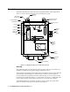
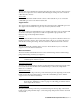
Description This section describes the components of the sample-draw detector. The sample-draw detector consists of the housing, flow system, and detection system. Mounting Foot, 4X Flow Adjust Potentiometer Flow Alarm Setpoint Adjustment Screw.
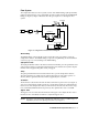
Flow System The sample-draw detector’s flow system consists of the INLET fitting, hydrophobic filter, pump, flowmeter, bypass valve, status lights, pressure switch, flow block, and EXHAUST fitting (see Figure 1). Figure 2 illustrates how the gas sample moves through the flow system.
Status Lights Two status lights are above the flowmeter. They are also visible through the window in the housing door. Pilot light The green Pilot light is on when the sample-draw detector is receiving power from the controller. Fail light The red Fail light is on when the sample flow rate is below the low flow level. NOTE: The factory set low flow level is 0.6 SCFH (±0.2). See “Adjusting the Low Flow Setting” on page 15 to adjust this setting.
Connector The top of the sensor includes five pins that plug into the socket connector. This connector allows you to replace the sensor without disconnecting the wiring. The sensor leads are soldered to the connector. Sensor leads Four color-coded leads extend from the connector. The leads allow you to connect the combustible gas sensor to the main circuit board. Oxygen Sensor The oxygen sensor is installed in the flow block to the right of the combustible gas sensor.
NOTE: The pump and pressure switch are factory-wired to the circuit board. See “Installation” on page 7 for all wiring procedures related to the sample-draw detector. Relay The relay is to the left of the detector terminal strip. The relay is single-pole, double-throw (SPDT) and is rated for 2 amps at 25 VDC (resistive). If the pressure switch senses a low flow condition, the relay interrupts the signal from the combustible gas sensor.
Installation This section describes procedures to mount the sample-draw detector in the monitoring environment and wire the sample-draw detector to a controller. Mounting the Sample-Draw Detector 1. Select the mounting site. Consider the following when you select the mounting site.
5. Slightly loosen the screw that secures the mounting foot to the housing, then rotate the mounting foot 180 degrees (see Figure 3). 6. Tighten the screw that secures the mounting foot to the housing. 7. Repeat steps 3 and 4 for the remaining three mounting feet. 8. Position the sample-draw housing on a vertical surface at eye level (4 1/2 to 5 feet from the floor). 9. Insert 1/4 inch or 5/16 inch screws through the slots in the mounting feet to secure the housing to the mounting surface.
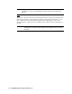
CAUTION: Do not route controller power wiring and detector wiring through the same hub. The power cable may disrupt the transmission of the sensor signal to the controller. 8. Connect the wires to the applicable detector terminal strip and power terminals at the controller as shown in Figure 4. See the 35-3000RK-LEL/O detector head specification sheet for your controller for the specific wiring connections to the controller. LEL/Oxygen Sample Draw Housing PUMP ASSY INTERN ALLY WIRED .
Start Up This section describes procedures to start up the sample-draw detector and place the sample-draw detector into normal operation. Introducing Incoming Power 1. Complete the installation procedures described earlier in this manual. 2. Verify that the wiring is correct and secure. Refer to the controller operator’s manual for connections at the controller. 3. Turn on or plug in the power to the controller, then turn on the controller. 4.
for the oxygen channel, continue with step 3. 3. Perform a zero operation at the controller. See the controller operator’s manual for instructions to perform a zero operation. Maintenance This section describes maintenance procedures. It includes preventive maintenance procedures. This section also includes procedures to troubleshoot the sample-draw detector, replace components of the sample-draw detector, and adjust the low flow setting.
Performing the response test 1. Screw the demand flow regulator into the combustible gas calibration cylinder. 2. Connect the calibration tubing from the regulator to the INLET fitting. Gas will begin to flow. 3. After approximately one minute, verify that the reading at the controller stabilizes within ± 20% of the concentration of the test sample. If the reading is not within ± 20% of the test sample, calibrate the sample-draw detector as described in the Calibration section. 4.
6. If the fail condition continues, contact RKI Instruments, Inc. for further instruction. Slow or No Response/Difficult or Unable to Calibrate Symptoms • The sensors respond slowly or do not respond during the monthly response test. • Unable to accurately set the zero or response reading during the calibration procedure. • The sensors require frequent calibration. Probable causes • The calibration cylinder is low, out-dated, or defective.
11. Turn on the controller. CAUTION: Allow the replacement sensor to warm up for 15 minutes before you continue. 12. Calibrate the replacement sensor as described in “Calibration, Combustible Sensor” on page 16. Replacing the Oxygen Sensor 1. Turn off the controller. 2. Turn off power to the controller. 3. Open the housing door of the sample-draw detector. 4. Unscrew and remove the two screws that secure the sensor retaining plate, then lift the plate, connector, and sensor out of the housing. 5.
6. Insert the cone-shaped front ferrule on top of the bottom ferrule. Insert the ferrule so the smaller end of the cone is facing up. 7. Screw the nut onto the fitting by hand just until it stops turning. 8. Insert the sample tubing into the fitting until it bottoms out. 9. Firmly tighten the nut so the ferrules crimp onto the sample tubing and make a seal.
Calibration, Combustible Sensor This section describes how to calibrate the combustible sensor in the sample-draw detector. It includes procedures to prepare for calibration, set the zero reading, set the response reading, and return to normal operation. The standard calibration gas for the sample-draw detector is methane. The sample-draw detector may be calibrated to other combustible gases such as hexane or hydrogen. Use the correct calibration gas for your installation.
Returning to Normal Operation 1. Reconnect the incoming sample line. 2. Wait approximately one minute to allow the combustible gas reading to stabilize. 3. Follow the instructions in the controller’s operator’s manual to exit the calibration mode. 4. Store the components of the calibration kit in a safe and convenient place. Calibration, Oxygen Sensor This section describes how to calibrate the oxygen sensor in the sample-draw detector.
5. Disconnect the sample tubing from the sample-draw detector’s inlet fitting. 6. Reconnect the incoming sample line to the inlet fitting. 7. Unscrew the regulator from the calibration cylinder. Returning to Normal Operation 1. Wait 1 to 2 minutes to allow the oxygen reading at the controller to return to normal, then return the controller to normal operation. NOTE: If you do not allow the oxygen reading to return to normal, then unwanted alarms may occur. 2.
Parts List Table 2 lists replacement parts and accessories for the sample-draw detector. Table 2: Parts List Part Number Description 06-1248RK Sample tubing, 3/16 x 5/16, specify length, (for calibration kit) 17-2593RK Brass insert for flexible 1/4 OD x .