35-3000RK-LEL Combustible Gas Sample-Draw Detector Operator’s Manual Part Number: 71-0104RK Revision: P1 Released: 9/18/04 RKI Instruments Inc. 33248 Central Ave. Union City, CA 94587 PH: 800-754-5165 Fax: 510-441-5650 www.rkiinstruments.
Product Warranty RKI Instruments, Inc., warrants gas alarm equipment sold by us to be free from defects in materials, workmanship, and performance for a period of one year from date of shipment from RKI Instruments, Inc. Any parts found defective within that period will be repaired or replaced, at our option, free of charge.
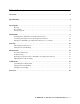
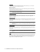
Table of Contents Overview . . . . . . . . . . . . . . . . . . . . . . . . . . . . . . . . . . . . . . . . . . . . . . . . . . . . . . . . . . . . . . . . . . . 4 Specifications . . . . . . . . . . . . . . . . . . . . . . . . . . . . . . . . . . . . . . . . . . . . . . . . . . . . . . . . . . . . . . . . 4 Description . . . . . . . . . . . . . . . . . . . . . . . . . . . . . . . . . . . . . . . . . . . . . . . . . . . . . . . . . . . . . . . . . . 5 Housing . . . . . . . . . . . . . . . . . . . . . . . . .
Overview This operator’s manual describes the combustible gas sample-draw detector. This manual also describes how to install, start up, maintain, and calibrate the sample-draw detector when using it with a gas monitoring controller. A parts list at the end of this manual lists replacement parts and accessories for the sample-draw detector. Specifications Table 1 lists specifications for the combustible gas sample-draw detector.
Description This section describes the components of the combustible gas sample-draw detector. The sample-draw detector consists of the housing, flow system, and detection system.
Flow System The sample-draw detector’s flow system consists of the INLET fitting, hydrophobic filter, pump, flowmeter, bypass valve, status lights, pressure switch, and EXHAUST fitting (see Figure 1). Figure 2 illustrates how the gas sample moves through the flow system.
Status lights Two status lights are above the flowmeter. They are also visible through the window in the housing door. Pilot light The green Pilot light is on when the sample-draw detector is receiving power from the controller. Fail light The red Fail light is on when the sample flow rate is below the low flow level. NOTE: The factory set low flow level is 0.6 SCFH (±0.2). See “Adjusting the Low Flow Setting” on page 17 to adjust this setting.
Sensor leads Four color-coded leads extend from the connector. The leads allow you to connect the combustible gas sensor to the main circuit board. Main Circuit Board The main circuit board includes the interconnect terminal strip, detector terminal strip, pump terminal strip, and relay (see Figure 1). NOTE: The flowmeter and status lights are mounted to the main circuit board but are considered part of the flow system.
Installation This section describes procedures to mount the sample-draw detector in the monitoring environment and wire the sample-draw detector to a controller. Mounting the Sample-Draw Combustible Gas Detector 1. Select the mounting site. Consider the following when you select the mounting site.
NOTE: The sample-draw detector is shipped with the mounting feet “tucked under” the housing to protect the mounting feet during shipment. 5. Slightly loosen the screw that secures the mounting foot to the housing, then rotate the mounting foot 180 degrees (see Figure 3). 6. Tighten the screw that secures the mounting foot to the housing. 7. Repeat steps 3 and 4 for the remaining three mounting feet. 8.
CAUTION: If using shielded cable, leave the cable shield’s drain wire insulated and disconnected at the sample-draw detector. You will connect the opposite end of the drain wire at the controller. 7. Route the cable or wires in conduit leading from the sample-draw detector through one of the conduit hubs at the controller. CAUTION: Do not route controller power wiring and detector wiring through the same hub. The power cable may disrupt the transmission of the sensor signal to the controller. 8.
5. Connect the cable shield to an available chassis ground at the controller. The grounding screw on one of the controller’s grounded conduit hubs is an example of a chassis ground. Start Up This section describes procedures to start up the sample-draw detector and place the sample-draw detector into normal operation. Introducing Incoming Power 1. Complete the installation procedures described earlier in this manual. 2. Verify that the wiring is correct and secure.
3. Perform a zero operation at the controller. See the controller operator’s manual for instructions to perform a zero operation. Maintenance This section describes maintenance procedures. It includes preventive maintenance procedures. This section also includes procedures to troubleshoot the sample-draw detector, replace components of the sample-draw detector, and adjust the low flow setting.
3. Disconnect the incoming sample line from the sample-draw detector’s inlet fitting, then connect the sample tubing from the gas collection bag to the inlet fitting. Allow the sample-draw pump to draw out any residual gas in the gas collection bag. 4. Close the tubing clamp. NOTE: This step will cause a low flow alarm. 5. Disconnect the calibration kit sample tubing from the inlet fitting.
Fail condition Symptoms • The sample-draw detector’s Fail light is on. • The monitoring device is operating properly but indicates a reading well below zero. Probable causes • The sample-draw detector’s flow rate is too low because of an obstructed sample line, failed pump, etc. • The sample-draw detector is malfunctioning. • The sensor wiring is disconnected or misconnected. Recommended action 1.
6. If the calibration/response difficulties continue, contact RKI Instruments, Inc., for further instruction. Replacing Components of the Combustible Gas Sample-draw Detector This section includes procedures to replace the sensor, hydrophobic filter, and ferrules. Replacing the combustible gas sensor 1. Turn off the controller 2. Turn off power to the controller. 3. Open the housing door of the sample-draw detector. 4.
NOTE: Make sure the bottom ferrule is laying flat in the nut. 6. Insert the cone-shaped front ferrule on top of the bottom ferrule. Insert the ferrule so the smaller end of the cone is facing up. 7. Screw the nut onto the fitting by hand just until it stops turning. 8. Insert the sample tubing into the fitting until it bottoms out. 9. Firmly tighten the nut so the ferrules crimp onto the sample tubing and make a seal.
Calibration This section describes how to calibrate the combustible gas sample-draw detector. It includes procedures to assemble the calibration kit, set the zero reading, set the response reading, and return to normal operation. The standard calibration gas for the sample-draw detector is methane. The sample-draw detector may be calibrated to other combustible gases such as hexane or hydrogen. Use the correct calibration gas for your installation.
Setting the Zero Reading 1. Open the tubing clamp, then connect the sample tubing from the gas collection bag to the sample-draw detector’s inlet line. This step is not necessary if you verified a fresh air environment earlier in this procedure. 2. Allow the sample-draw detector to draw sample for one minute. 3. Follow the directions in the controller’s operator’s manual for setting the zero reading. If you used a zero air calibration cylinder to set the zero reading, proceed to step 4.
Parts List Table 2 lists replacement parts and accessories for the sample-draw combustible gas detector. Table 2: Parts List Part Number Description 06-1248RK Sample tubing, 3/16 x 5/16, specify length, (for calibration kit) 17-2593RK Brass insert for flexible 1/4 OD x .