35-3000RK-OXY Oxygen Sample-Draw Detector Operator’s Manual Part Number: 71-0071RK Revision: P1 Released: 7/18/02 www.rkiinstruments.com RKI Instruments Inc.
Product Warranty RKI Instruments, Inc., warrants gas alarm equipment sold by us to be free from defects in materials, workmanship, and performance for a period of one year from date of shipment from RKI Instruments, Inc. Any parts found defective within that period will be repaired or replaced, at our option, free of charge.
Table of Contents Overview . . . . . . . . . . . . . . . . . . . . . . . . . . . . . . . . . . . . . . . . . . . . . . . . . . . . . . . . . . . . . . . . . . . 4 Specifications . . . . . . . . . . . . . . . . . . . . . . . . . . . . . . . . . . . . . . . . . . . . . . . . . . . . . . . . . . . . . . . . 4 Description . . . . . . . . . . . . . . . . . . . . . . . . . . . . . . . . . . . . . . . . . . . . . . . . . . . . . . . . . . . . . . . . . . 5 Housing . . . . . . . . . . . . . . . . . . . . . . . . .
Overview This instruction manual describes the 35-3000RK-OXY sample-draw oxygen detector. This manual also describes how to install, start up, maintain, and calibrate the sample-draw detector when using it with a gas monitoring controller. A parts list at the end of this manual lists replacement parts and accessories for the sample-draw oxygen detector.
Description This section describes the components of the sample-draw oxygen detector. The sampledraw detector consists of the housing, flow system, and detection system.
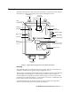
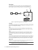
Flow System The sample-draw detector’s flow system consists of the inlet fitting, filter, pump, flowmeter, bypass valve, status lights, pressure switch, and exhaust fitting (see Figure 1). Figure 2 illustrates how the gas sample moves through the flow system. To Exhaust Bypass Valve Flowmeter Inlet Filter Pump Sensor Pressure Switch Figure 2: Sample-draw Oxygen Detector Flow Diagram Inlet fitting The inlet fitting on the right side of the housing allows the gas sample to enter the sampledraw detector.
Status lights Two status lights are above the flowmeter. They are also visible through the window in the housing door. Pilot light The green Pilot light is on when the sample-draw detector is receiving power from the Controller. Fail light The red fail light is on when the sample flow rate is below the low flow level NOTE: The factory set low flow level is 0.6 SCFH (±0.2). See “Adjusting the Low Flow Setting” on page 16 to adjust this setting.
Main Circuit Board The main circuit board includes the interconnect terminal strip, detector terminal strip, pump terminal strip, and relay (see Figure 1). NOTE: The flowmeter and status lights are mounted to the main circuit board but are considered part of the flow system. Interconnect terminal strip The interconnect terminal strip is the nine-point terminal strip near the bottom edge of the main circuit board. Use the interconnect terminal strip to connect the sample-draw detector to a controller.
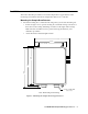
Installation This section describes procedures to mount the sample-draw oxygen detector in the monitoring environment and wire the sample-draw detector to a controller. Mounting the Sample-Draw Detector 1. Select the mounting site. Consider the following when you select the mounting site.
2. Close and latch the housing door. NOTE: The sample-draw detector is shipped with the mounting feet “tucked under” the housing to protect the mounting feet during shipment. 3. Slightly loosen the screw that secures the mounting foot to the housing, then rotate the mounting foot 180 degrees (see Figure 3). 4. Tighten the screw that secures the mounting foot to the housing. 5. Repeat steps 3 and 4 for the remaining three mounting feet. 6.
CAUTION: If using shielded cable, leave the cable’s drain wire insulated and disconnected at the sample-draw detector. You will connect the opposite end of the drain wire at the controller. 7. Route the cable or wires in conduit leading from the sample-draw detector through one of the conduit hubs on the controller. CAUTION: At the controller, do not route controller power and sample-draw detector wiring through the same conduit hub.
Start Up This section describes procedures to start up the sample-draw oxygen detector and place the sample-draw detector into normal operation. Introducing Incoming Power 1. Complete the installation procedures described earlier in this manual. 2. Verify that the power wiring is correct and secure. Refer to the controller instruction manual for connections at the controller. 3. Turn on or plug in the incoming power at the power source end, then turn on the controller. 4.
Maintenance This section describes maintenance procedures. It includes preventive maintenance procedures. This section also includes procedures to troubleshoot the sample-draw detector, replace components of the sample-draw detector, and adjust the low flow setting. Preventive Maintenance This section describes a preventive maintenance schedule to ensure the optimum performance of the sample-draw detector. It includes daily, monthly, and quarterly procedures. Daily 1. Verify that the pilot light is on.
Troubleshooting The troubleshooting guide describes symptoms, probable causes, and recommended action for problems you may encounter with the sample-draw detector. NOTE: This troubleshooting guide describes sample-draw detector problems only. See the controller instruction manual for problems you may encounter with the controller. Fail condition Symptoms • The sample-draw detector’s FAIL light is on. • The controller is operating properly but indicates a reading well below zero.
Recommended action 1. Verify that the calibration cylinder contains an adequate supply of a fresh test sample. 2. If necessary, set the correct flow rate with the bypass valve or flow adjust potentiometer. 3. If you cannot set the correct flow rate, check the sample line for obstructions or kinks. 4. If the calibration/response difficulties continue, replace the oxygen sensor as described later in this section. 5. If the calibration/response difficulties continue, contact RKI Instruments, Inc.
Replacing the ferrules Both the inlet and exhaust fittings include two ferrules that seal the inlet or exhaust tubing to the fitting. Replace the ferrules if the seal is bad or if you replace the sample tubing. Always replace the ferrules as a pair. 1. Disconnect the sample tubing from the fitting, then unscrew the nut from the fitting. 2. Verify that the ferrules did not remain in the nut. If necessary, remove the ferrules from the nut. 3.
Calibration This section describes how to calibrate the sample-draw oxygen detector. It includes procedures to assemble the calibration kit, set the fresh air reading, set the zero reading, and return to normal operation. NOTE: Calibrating the sample draw detector may cause alarms. Be sure to put the controller into its calibration program or disable external alarms before continuing. NOTE: This procedure describes calibration using a gas collection bag.
Setting the Zero Reading 1. Screw the dispensing valve onto the 100% N2 calibration cylinder. 2. Connect the sample tubing from the gas collection bag to the dispensing valve, then open the tubing clamp. 3. Open the dispensing valve. The gas collection bag begins to fill. 4. Close the dispensing valve when the gas collection bag appears full. 5. Close the tubing clamp, then disconnect the sample tubing from the dispensing valve.
Parts List Table 3 lists replacement parts and accessories for the sample-draw oxygen detector.