35-3000RKA-LEL Sample Draw Combustible Gas Detector Specifications Table 1 lists specifications for the sample draw combustible gas detector. Table 1: Specifications Target Gas Combustible Gas Input Power 24 VDC Construction (housing) Fiberglass/polyester (NEMA 4X) Dimensions 8.5 in. H x 6.5 in. W x 4.25 in. D Weight 4.5 lbs. Sampling Method sample draw Sample Flow 1.
Description This section describes the components of the sample draw combustible gas detector. The sample draw detector consists of the housing, flow system, and detection system.
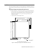
Flow System The sample draw detector’s flow system consists of the INLET fitting, filter, pump, flowmeter, bypass valve, status lights, pressure switch, and EXHAUST fitting (see Figure 1). Figure 2 illustrates how the gas sample moves through the flow system.
Status lights Two status lights are above the flowmeter. They are also visible through the window in the housing door. Pilot light The green Pilot light is on when the sample draw detector is receiving power. Fail light The red Fail light is on when the sample flow rate is below the low flow level. NOTE: The default low flow level is 0.6 SCFH (±0.2). See “Adjusting the Low Flow Setting” on page 15 to adjust this setting.
Connector The top of the sensor includes five pins that plug into the socket connector. This connector allows you to replace the sensor without disconnecting the wiring. The sensor leads are soldered to the connector. Sensor leads Four color-coded leads extend from the connector. The leads allow you to connect the combustible gas sensor to the main circuit board. Transmitter The transmitter is mounted to the left of the combustible sensor.
Pump terminal strip The pump terminal strip is the four-point terminal strip near the top edge of the circuit board. Use the pump terminal strip to connect the pump and pressure switch to the main circuit board. NOTE: The pump and pressure switch are factory-wired to the circuit board. See the “Installation” on page 7 for all wiring procedures related to the sample draw detector. Relay The relay is to the left of the detector terminal strip.
Installation This section describes procedures to mount the sample draw combustible gas detector in the monitoring environment and wire the sample draw detector to power and an external device. Mounting the Sample draw Combustible Gas Detector 1. Select the mounting site. Consider the following when you select the mounting site.
2. Close and latch the housing door. NOTE: The sample draw detector is shipped with the mounting feet “tucked under” the housing to protect the mounting feet during shipment. 3. Slightly loosen the screw that secures the mounting foot to the housing, then rotate the mounting foot 180 degrees (see Figure 3). 4. Tighten the screw that secures the mounting foot to the housing. 5. Repeat steps 3 and 4 for the remaining three mounting feet. 6.
5. Route the cable or wires in conduit leading from the sample draw detector to the recording or monitoring device and power. 6. Connect the cable shield to an available chassis ground at the device end. LEL Sam pl e Draw Housing Transmitte r, In terna lly Wired TP + POWER/SIG P/N 57-1050RK REV. 0 GND 24V 4-20 W HI TE RED SENSOR RED WHT GRN BLK TP SPAN ZERO LEL DETECTO R IN SAMPLE CHAMBER (INT ERNALLY WIRED) BLAC K GREEN PUMP ASSY INTERNALLY WIRED PRES SURE SWITCH INTERNALLY WIRED.
Start Up This section describes procedures to start up the sample draw combustible gas detector and place the sample draw detector into normal operation. Introducing Incoming Power 1. Complete the installation procedures described earlier in this manual. 2. Verify that the power/device wiring is correct and secure. 3. Turn on or plug in the incoming power at the power source end. 4. Verify that the Pilot light is on. 5. Verify that the flowmeter indicates a flow rate of approximately 1.5 SCFH.
Maintenance This section describes maintenance procedures. It includes preventive maintenance procedures. This section also includes procedures to troubleshoot the sample draw detector, replace components of the sample draw combustible gas detector, and adjust the low flow setting. Preventive Maintenance This section describes a preventive maintenance schedule to ensure the optimum performance of the sample draw detector. It includes daily, monthly, and quarterly procedures. Daily 1.
8. When the bag is full, unscrew the fixed flow regulator form the cylinder. 9. Close the clamp, then disconnect the sample tubing from the fixed flow regulator. Performing the response test 1. Connect the calibration tubing from the gas collection bag to the inlet line at or near the INLET fitting. The sample draw detector’s pump automatically begins pulling the test sample from the gas collection bag when you connect the tubing to the inlet line. 2.
Slow or no response/difficult or unable to calibrate Symptoms • The detector responds slowly or does not respond during the monthly response test. • Unable to accurately set the zero or response reading during the calibration procedure. • The detector requires frequent calibration. NOTE: Under “normal” circumstances, the detector requires calibration once a quarter. Some applications may require a more frequent calibration schedule.
Replacing Components of the Combustible Gas Sample Draw Detector This section includes procedures to replace the sensor, filter, and ferrules. Replacing the combustible gas sensor 1. Turn off incomming power. 2. Open the housing door of the sample draw detector. 3. Unscrew and remove the two screws that secure the retraining plate, then lift the plate, connector, and sensor out of the housing. 4. Unplug the connector from the sensor. 5.
Adjusting the Low Flow Setting The factory-set low flow setting is 0.6 SCFH (±0.2). To adjust the low flow setting: 1. Use the flow adjust potentiometer (VR1) to set the flow to 0.6 SCFH. If the sample draw detector goes into low flow alarm before you can adjust the flow down to 0.6 SCFH, adjust the low flow potentiometer 1/4 turn clockwise, then attempt to set the flow again. Repeat this step until you are able to adjust the flow to 0.6 SCFH. 2.
Calibration This section describes how to calibrate the sample draw combustible gas detector. It includes procedures to assemble the calibration kit, set the zero reading, set the response reading, and return to normal operation. NOTE: This procedure describes calibration using a gas collection bag. A demand flow calibration kit is also available for calibrating the combustible gas sample draw detector. Preparing for Calibration NOTE: Calibrating the sample draw adapter may cause alarms.
5. Connect the tubing from the gas collection bag to the fixed flow regulator, then open the clamp. 6. Screw the fixed flow regulator onto the zero air calibration cylinder. The gas collection bag begins to fill. 7. When the bag is full, unscrew the fixed flow regulator from the cylinder. 8. Close the clamp, then disconnect the sample tubing from the fixed flow regulator. Setting the Zero Reading 1.
Parts List Table 4 lists replacement parts and accessories for the sample draw combustible gas detector.