35-3001-06-01 Combustible Gas/Oxygen Sample-Draw Detector Operator’s Manual Part Number: 71-0292RK Revision: P7 Released: 9/17/14 www.rkiinstruments.
WARNING Read and understand this instruction manual before operating detector. Improper use of the detector could result in bodily harm or death. Periodic calibration and maintenance of the detector is essential for proper operation and correct readings. Please calibrate and maintain this detector regularly! Frequency of calibration depends upon the type of use you have and the sensor types.
Product Warranty RKI Instruments, Inc. warrants gas alarm equipment sold by us to be free from defects in materials, workmanship, and performance for a period of one year from date of shipment from RKI Instruments, Inc. Any parts found defective within that period will be repaired or replaced, at our option, free of charge.
Table of Contents Overview . . . . . . . . . . . . . . . . . . . . . . . . . . . . . . . . . . . . . . . . . . . . . . . . . . . . . . . . . . . . . . . . . . . . 1 Specifications . . . . . . . . . . . . . . . . . . . . . . . . . . . . . . . . . . . . . . . . . . . . . . . . . . . . . . . . . . . . . . . . . 1 Description. . . . . . . . . . . . . . . . . . . . . . . . . . . . . . . . . . . . . . . . . . . . . . . . . . . . . . . . . . . . . . . . . . . 2 External Components. . . . . . . . . . . . . . . .
Overview This operator’s manual describes the 35-3001-06-01 combustible gas/oxygen sample-draw detector. This manual also describes how to install, start up, maintain, and calibrate the sampledraw detector when using it with a gas monitoring controller. A parts list at the end of this manual lists replacement parts and accessories for the sample-draw detector. Specifications Table 1 lists specifications for the combustible gas/oxygen sample-draw detector.
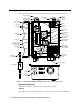
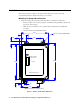
Description This section describes the components of the combustible gas/oxygen sample-draw detector.
installation where general purpose equipment is in use. The housing door is hinged on the left side and is secured by two latches on the right side. The flowmeter and status LEDs are visible through a window in the housing door. Four mounting feet are attached to the back of the housing (one at each corner). Use the mounting feet to install the housing to a vertical surface. Sample Fittings The sample fittings are located on the left side of the bottom of the housing.
Detector/Amp Terminal Strip The detector/amp terminal strip is the upper twelve-point terminal strip in the bottom right corner of the main circuit board. Use the detector/amp terminal strip to connect the combustible gas sensor to the main circuit board. NOTE: The combustible gas sensor is factory-wired to the main circuit board. See the “Installation” section on page 6 for all wiring procedures related to the sample-draw detector.
Sensor Flow Control Valve The sensor flow control valve is mounted to the flowmeter circuit board above the flowmeter. The sensor flow control valve adjusts the flow rate to the detector. Turn the valve’s knob clockwise to increase the flow and counterclockwise to decrease the flow. Status LEDs Two status LEDs are above the flowmeter. They are also visible through the window in the housing door. The green Pilot LED is on when the sample-draw detector is receiving power from the controller.
Installation This section describes procedures to mount the sample-draw detector in the monitoring environment and wire the sample-draw detector to a controller. Mounting the Sample-Draw Detector 1. Select the mounting site. Consider the following when you select the mounting site: • Is there enough room to open the housing door and make wiring and tubing connections at the bottom of the housing? • Make sure there is sufficient room to perform start-up, maintenance, and calibration procedures.
2. Close and latch the housing door. NOTE: The sample-draw detector is shipped with the mounting feet “tucked under” the housing to protect the mounting feet during shipment. 3. Slightly loosen the screw that secures the mounting foot to the housing, then rotate the mounting foot 180 degrees (see Figure 3). 4. Tighten the screw that secures the mounting foot to the housing. 5. Repeat steps 3 and 4 for the remaining three mounting feet. 6.
ring, if it came out, in the orientation shown in Figure 4. 4. Screw the inlet fitting tube nut back onto the fitting body. See the next section for instructions to install a new piece of tubing into the fitting. Connecting the Sample Lines to the Sample-Draw Detector See Figure 4 for the fitting layout. Installing the Inlet Line with Particle Filter 1. Connect the particle filter to the tubing stub on the inlet by pushing the flexible tubing on the filter onto the stub.
Installing the Exhaust Line 1. Loosen the nut on the exhaust fitting until 3 threads are visible. 2. Push 1/4” O.D. rigid polypropylene or rigid Teflon sample tubing into the fitting until it stops. Flexible polyurethane tubing may be used with an appropriate insert. RKI Instruments, Inc. recommends using either 1/4” O.D. x 1/8” I.D. or 1/4” O.D. x 0.170” I.D. tubing based on your length requirements. See “Specifications” on page 1 for maximum tubing lengths based on tubing size.
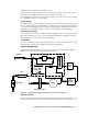
8. Connect the wires to the applicable detector/transmitter terminal strip at the controller as shown in Figure 5. Refer to the controller operator’s manual and the controller detector head specification sheet for the 35-3001-06-01 for detector/terminal strip connections specific to the controller.
Start Up This section describes procedures to start up the sample-draw detector and place the sample-draw detector into normal operation. Introducing Incoming Power 1. Complete the installation procedures described earlier in this manual. 2. Verify that the wiring is correct and secure. Refer to the controller operator’s manual for connections at the controller. 3. Turn on or plug in the power to the controller, then turn on the controller. 4. Verify that the sample-draw detector’s Pilot LED is on.
reading is not 0 %LEL for the combustible channel or 20.9% for the oxygen channel, continue with step 3. 3. Perform a zero (fresh air) operation at the controller. See “Setting the Zero Reading” on page 17 (for IR LEL sensor), “Setting the Fresh Air Reading” on page 18 (for oxygen sensor), and the controller operator’s manual for instructions to perform a zero (fresh air) operation. Maintenance This section describes maintenance procedures. It includes preventive maintenance procedures.
2. Connect the calibration tubing from the demand flow regulator to the inlet fitting. Gas will begin to flow. 3. After approximately one minute, verify that the combustible gas reading at the controller stabilizes within ± 20% of the concentration of the test sample. If the reading is not within ± 20% of the test sample, calibrate the sample-draw detector as described in “Calibration, IR LEL Sensor” on page 17.
4. Calibrate the sample-draw detector as described in “Calibration, IR LEL Sensor” on page 17 and “Calibration, Oxygen Sensor” on page 18. 5. If the fail condition continues, replace the sensor(s) as described in “Replacing Components of the Sample-Draw Detector” on page 14. 6. If the fail condition continues, contact RKI Instruments, Inc. for further instruction.
8. Secure the sensor PCB on the flow block with the four screws you removed in step 4. 9. Close and latch the housing door. 10. Turn on power to the controller. 11. Turn on the controller. CAUTION: Allow the replacement sensor to warm up for 5 minutes before you continue. 12. Calibrate the replacement sensor as described in “Calibration, IR LEL Sensor” on page 17. Replacing the Oxygen Sensor 1. Turn off the controller. 2. Turn off power to the controller. 3.
4. Reinstall the tubing routed to the sampling area. Adjusting the Low Flow Setting NOTE: Adjusting the low flow setting will cause a low flow alarm at the sample-draw detector and a fail alarm at the controller. Be sure to put the controller into its calibration program or disable external alarms before performing this test. The factory-set low flow setting is 0.6 SCFH (±0.1). To adjust the low flow setting: 1. Use the sensor flow control valve to set the flow to 0.6 SCFH.
Calibration, IR LEL Sensor This section describes how to calibrate the IR combustible gas sensor of the sample-draw detector. It includes procedures to prepare for calibration, set the zero reading, set the response reading, and return to normal operation. The standard calibration gas for the combustible gas sensor is methane. The sample-draw detector may be calibrated to other combustible gases such as hexane or hydrogen. Use the correct calibration gas for your installation.
Calibration, Oxygen Sensor This section describes how to calibrate the oxygen sensor in the sample-draw detector. It includes procedures to prepare for calibration, set the fresh air reading, set the zero reading, and return to normal operation. NOTE: Calibrating the sample draw detector may cause alarms. Be sure to put the controller into its calibration program or disable external alarms before continuing. NOTE: This procedure describes calibration using a demand flow regulator.
2. Verify that the controller display reading stabilizes at 20.9%. 3. Store the components of the calibration kit in a safe and convenient place. Parts List Table 2 lists replacement parts and accessories for the sample-draw detector.