35-3001A-05-02 Carbon Dioxide Sample-Draw Detector Operator’s Manual Part Number: 71-0340 Revision: P2 Released: 9/17/14 www.rkiinstruments.
WARNING Read and understand this instruction manual before operating detector. Improper use of the detector could result in bodily harm or death. Periodic calibration and maintenance of the detector is essential for proper operation and correct readings. Please calibrate and maintain this detector regularly! Frequency of calibration depends upon the type of use you have and the sensor types.
Product Warranty RKI Instruments, Inc. warrants gas alarm equipment sold by us to be free from defects in materials, workmanship, and performance for a period of one year from date of shipment from RKI Instruments, Inc. Any parts found defective within that period will be repaired or replaced, at our option, free of charge.
Table of Contents Overview . . . . . . . . . . . . . . . . . . . . . . . . . . . . . . . . . . . . . . . . . . . . . . . . . . . . . . . . . . . . . . . . . . . . 1 Specifications . . . . . . . . . . . . . . . . . . . . . . . . . . . . . . . . . . . . . . . . . . . . . . . . . . . . . . . . . . . . . . . . . 1 Description. . . . . . . . . . . . . . . . . . . . . . . . . . . . . . . . . . . . . . . . . . . . . . . . . . . . . . . . . . . . . . . . . . . 2 External Components. . . . . . . . . . . . . . . .
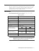
Overview This operator’s manual describes the 35-3001A-05-02 carbon dioxide sample-draw detector. This manual also describes how to install, start up, maintain, and calibrate the sample-draw detector when using it with a gas monitoring controller. A parts list at the end of this manual lists replacement parts and accessories for the sample-draw detector. Specifications Table 1 lists specifications for the carbon dioxide sample-draw detector.
Description This section describes the components of the carbon dioxide sample-draw detector.
External Components This section describes the sample-draw detector’s external components. Housing The sample-draw detector’s fiberglass housing is weather- and corrosion-resistant. It is suitable for installation where general purpose equipment is in use. The housing door is hinged on the left side and is secured by two latches on the right side. The flowmeter and status LEDs are visible through a window in the housing door. Four mounting feet are attached to the back of the housing (one at each corner).
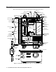
Main Circuit Board The main circuit board includes the detector/amp terminal strip, interconnect terminal strip, oxygen sensor terminal strip, pump connector, and flowmeter circuit board connector (see Figure 1). Detector/Amp Terminal Strip The detector/amp terminal strip is the upper twelve-point terminal strip in the bottom right corner of the main circuit board. Use the detector/amp terminal strip to connect the amplifier to the main circuit board.
counterclockwise to increase the flow and clockwise to decrease the flow. Status LEDs Two status LEDs are above the flowmeter. They are also visible through the window in the housing door. The green Pilot LED is on when the sample-draw detector is receiving power from the controller. The red Fail LED is on when the sample flow rate is below the low flow level. Pressure Switch The pressure switch is mounted to the back of the flowmeter circuit board.
Span Pot The span pot is located below the zero pot (see Figure 1). Use a small flat blade screwdriver to turn the span pot’s adjustment screw and adjust the amplifier’s gas response output during the calibration procedure. Turn the adjustment screw clockwise to increase the span output and counterclockwise to decrease the span output. CAUTION: The amplifier includes additional pots. They are factory-set. Do not adjust them.
Installation This section describes procedures to mount the sample-draw detector in the monitoring environment and wire the sample-draw detector to a controller. Mounting the Carbon Dioxide Sample-Draw Detector 1. Select the mounting site.
2. Close and latch the housing door. NOTE: The sample-draw detector is shipped with the mounting feet “tucked under” the housing to protect the mounting feet during shipment. 3. Slightly loosen the screw that secures the mounting foot to the housing, then rotate the mounting foot 180 degrees (see Figure 3). 4. Tighten the screw that secures the mounting foot to the housing. 5. Repeat steps 3 and 4 for the remaining three mounting feet. 6.
ring, if it came out, in the orientation shown in Figure 4. 4. Screw the inlet fitting tube nut back onto the fitting body. See the next section for instructions to install a new piece of tubing into the fitting. Connecting the Sample Lines to the Sample-Draw Detector See Figure 4 for the fitting layout. Installing the Inlet Line with Particle Filter 1. Connect the particle filter to the tubing stub on the inlet by pushing the flexible tubing on the filter onto the stub.
Installing the Exhaust Line 1. Loosen the nut on the exhaust fitting until 3 threads are visible. 2. Push 1/4” O.D. rigid polypropylene or rigid Teflon sample tubing into the fitting until it stops. Flexible polyurethane tubing may be used with an appropriate insert. RKI Instruments, Inc. recommends using either 1/4” O.D. x 1/8” I.D. or 1/4” O.D. x 0.170” I.D. tubing based on your length requirements. See “Specifications” on page 1 for maximum tubing lengths based on tubing size.
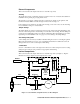
8. Connect the wires to the applicable detector/transmitter terminal strip at the controller as shown in Figure 5. Refer to the controller operator’s manual and the controller detector head specification sheet for the 35-3001A-05-02 for detector/terminal strip connections specific to the controller.
Start Up This section describes procedures to start up the sample-draw detector and place the sample-draw detector into normal operation. Introducing Incoming Power 1. Complete the installation procedures described earlier in this manual. 2. Verify that the wiring is correct and secure. Refer to the controller operator’s manual for connections at the controller. 3. Turn on or plug in the power to the controller, then turn on the controller. 4. Verify that the sample-draw detector’s Pilot LED is on.
(+) test point; plug the negative lead into the black (-) test point. 4. Screw the demand flow regulator into the 100% nitrogen calibration cylinder. 5. Connect the calibration tubing from the demand flow regulator to the inlet fitting. Gas will begin to flow. 6. Allow the sample-draw detector to draw sample for one minute. 7. Verify a voltmeter reading of 100 mV (± 2 mV). 8.
Preparing for the response test NOTE: This procedure describes the RKI calibration kit that includes a demand flow regulator. 1. Verify that the controller display reading for the channel you are testing is consistent with typical background levels of CO2. If the display reading is not consistent with typical background levels of CO2, set the zero reading of the transmitter as described in “Start Up” on page 12 of this manual, then continue this procedure. 2.
• The monitoring device is operating properly but indicates a reading well below zero or a failure alarm. Probable causes • The sample-draw detector’s flow rate is too low because of an obstructed sample line, failed pump, etc. • The sample-draw detector is malfunctioning. • The sensor and/or amplifier wiring is disconnected or misconnected. Recommended action 1. At the sample-draw detector, set the correct flow rate with the sensor flow control valve. 2.
Replacing Components of the Carbon Dioxide Sample-Draw Detector This section includes procedures to replace the sensor, hydrophobic filter, and particle filter. Replacing the Infrared Carbon Dioxide Sensor 1. Turn off the controller. 2. Turn off power to the controller. 3. Open the housing door of the sample-draw detector. 4. Unscrew and remove the four screws that secure the IR carbon dioxide sensor PCB, then lift the IR carbon dioxide sensor PCB and sensor off of the flow block.
Table 2:Reconnecting the Amplifier to the Detector/Amp Terminal Strip Amplifier Controller Terminal Strip Detector/Amp Terminal Strip on Main PCB PWR/SIG “S” S PWR/SIG “+” + Table 3:Reconnecting the IR Carbon Dioxide Sensor to the Amplifier Amplifier Detector Terminal Strip Detector Lead DETECTOR “R” RED DETECTOR “W” WHT DETECTOR “G” GREEN DETECTOR “B” BLK NOTE: When the sample-draw detector is first powered up with a new amplifier, the initial output may be either high or below zero dependi
Adjusting the Low Flow Setting NOTE: Adjusting the low flow setting will cause a low flow alarm at the sample-draw detector and a fail alarm at the controller. Be sure to put the controller into its calibration program or disable external alarms before performing this test. The factory-set low flow setting is 0.6 SCFH (±0.1). To adjust the low flow setting: 1. Use the sensor flow control valve to set the flow to 0.6 SCFH.
Calibration This section describes how to calibrate the carbon dioxide sample-draw detector. It includes procedures to prepare for calibration, set the zero reading, set the response reading, and return to normal operation. NOTE: This procedure describes calibration using a demand flow regulator. Preparing for Calibration 1. Follow the instructions in the controller’s operator’s manual for entering calibration mode. 2. Open the housing door. 3. Set a voltmeter to measure in the millivolt (mV) range.
6. Disconnect the sample tubing from the inlet line. 7. Unscrew the regulator from the carbon dioxide calibration cylinder. Returning to Normal Operation 1. Wait approximately one minute to allow the carbon dioxide reading to stabilize. 2. Remove the voltmeter leads from the amplifier test points. 3. Close the housing door. 4. Follow the instructions in the controller’s operator’s manual to exit the calibration mode. 5. Store the components of the calibration kit in a safe and convenient place.