35-3010RKA-04 Sample-Draw Detector Head Part Number: 71-0213RK Revision: D Released: 9/24/13 rkiinstruments.
WARNING Read and understand this instruction manual before operating detector. Improper use of the detector could result in bodily harm or death. Periodic calibration and maintenance of the detector is essential for proper operation and correct readings. Please calibrate and maintain this detector regularly! Frequency of calibration depends upon the type of use you have and the sensor types.
Product Warranty RKI Instruments, Inc. warrants gas alarm equipment sold by us to be free from defects in materials, workmanship, and performance for a period of one year from date of shipment from RKI Instruments, Inc. Any parts found defective within that period will be repaired or replaced, at our option, free of charge.
Table of Contents Overview . . . . . . . . . . . . . . . . . . . . . . . . . . . . . . . . . . . . . . . . . . . . . . . . . . . . . . . . . . . . . . . . . . . 1 Specifications. . . . . . . . . . . . . . . . . . . . . . . . . . . . . . . . . . . . . . . . . . . . . . . . . . . . . . . . . . . . . . . . 1 Description . . . . . . . . . . . . . . . . . . . . . . . . . . . . . . . . . . . . . . . . . . . . . . . . . . . . . . . . . . . . . . . . . . 2 Housing . . . . . . . . . . . . . . . . . . . . . . . . . .
Overview This manual describes the 35-3010RKA-04 sample-draw detector. This manual also describes how to install, start up, maintain, and calibrate the detector. A parts list at the end of this manual lists replacement parts and accessories for the sample-draw detector. Specifications Table 1 lists specifications for the 35-3010RKA-04.
Description This section describes the components of the 35-3010RKA-04 sample-draw detector. The sample-draw detector consists of the housing, flow system, and detection system.
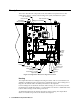
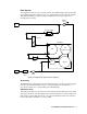
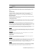
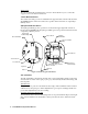
Flow System The sample-draw detector’s flow system consists of the INLET fitting, hydrophobic filter, charcoal filter, pump, flowmeter, bypass valve, status lights, pressure switch, flow block, and EXHAUST fitting (see Figure 1). Figure 2 illustrates how the gas sample moves through the flow system.
Charcoal Filter The charcoal filter is located above the LEL transmitter. It is held in place by a metal clip. The charcoal filter is placed after the H2S sensor and before the CO sensor in the flow system. It scrubs out interfering gases which may cause the CO sensor to respond, such as H2S or certain hydrocarbons. Replace the charcoal filter when false high CO readings are noticed, especially in the presence of H2S.
NOTE: There is no low flow indication for the LEL or oxygen channel in the 353010RKA-04. Flow Block The flow block is located in the lower right corner of the sample-draw detector. All the sensors are installed in the flow block. The flow block routes the sampled air to each sensor. EXHAUST Fitting The EXHAUST fitting on the bottom of the housing allows the gas sample to exit the sample-draw detector. The EXHAUST fitting accepts 1/4 in. rigid tubing.
Sensor Leads Two color-coded leads extend from the connector. The leads allow you to connect the oxygen sensor to the main circuit board. Carbon Monoxide Sensor The carbon monoxide gas sensor is installed in the upper left side of the flow block. In the 35-3010RKA-04, the carbon monoxide sensor position in the flow block is occupied by a dummy sensor. Hydrogen Sulfide Gas Sensor The hydrogen sulfide gas sensor position is located in the upper right side of the flow block.
Test Points The test points are located on the left side of the transmitter and are labeled TP+ and TP-. A 100 mV - 500 mV output is available at these test points for use during calibration. Oxygen Transmitter The oxygen transmitter is mounted to the right of the LEL transmitter and above the main circuit board. The amplifier includes the amplifier type selector, two internally wired terminal strips, span pot, zero pot, and test points.
Main Circuit Board Pump Terminal Stip Test Point CAL - 1 Fail LED Test Point CAL + 1 Flowmeter Test Point CAL - 2 Flow Adjust Pot Test Point CAL + 2 Low Flow Adjust Reset Switch Pilot LED Relay Pressure Switch Zero Span Amp 1 (CO) Interconnect Terminal Strip Zero Span Amp 2 (H2S) Sensor/Transmitter Terminal Strip AC Terminal Strip Not Used Figure 4: Main Circuit Board The main circuit board includes the interconnect terminal strip, sensor/transmitter terminal strip, amp 1 circuit, amp 2 cir
Amp 1 and Amp 2 Circuits These circuits are located to the left of the sensor/transmitter terminal strip. They each include test points, a zero pot, and a span pot. Amp 1 is on the left and is for the CO channel. Amp 2 is on the right and is for the H2S channel. The zero and span pots are used during calibration. Use the span pot to make adjustments to gas response readings and the zero pot to make adjustments to the zero reading.
Installation This section describes procedures to mount the sample-draw gas detector in the monitoring environment and wire the sample-draw detector to power and an external device. Mounting the Sample-Draw Detector 1. Select the mounting site. Consider the following when you select the mounting site.
5. Repeat steps 3 and 4 for the remaining three mounting feet. 6. Position the sample-draw housing on a vertical surface at eye level (4 1/2 to 5 feet from the floor). 7. Insert 1/4 in. or 5/16 in. screws through the slots in the mounting feet to secure the housing to the mounting surface. Connecting the Sample Lines to the Sample-Draw Detector 1. Attach 1/4 in. O.D. rigid polypropylene or rigid Teflon sample tubing to the INLET fitting.
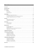
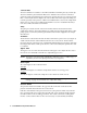
Sam ple Draw Housing Main Circuit Board Interconnect Terminal Strip Oxygen (Controller Transmitter Term inals) 24 VD C 4/2 0 (Fe edb ack) + 4/2 0 (Fe edb ack ) CO (Controller Transmitter Term inals) + 24 VD C 24 VD C + 4/2 0 (Fe edb ack) Figure 6: External (Field) Wiring, Sample-Draw Detector 12 • 35-3010RKA-04 Sample-Draw Detector LEL (Controller Transmitter Term inals)
TP+ GND T S E N UM S T R I N S ENSOR + FB 4 /20 2 4V 4-20 ZERO RED WHT SPAN GRN BLK TP- BATT 24V TP + + TP - POWER/SIG P/N 57 -1 05 0R K REV.
Start Up This section describes procedures to start up the sample-draw detector and place the sample-draw detector into normal operation. Introducing Incoming Power 1. Complete the installation procedures described earlier in this manual. 2. Verify that the power wiring to the controller is correct and secure. See controller operator’s manual. 3. Turn on or plug in the incoming power at the controller, then turn on the controller. 4. Verify that the controller is on and operating properly. 5.
Operation Normal Operation During normal operation, the Pilot LED will be on and the flowmeter will indicate about 1.2 SCFH. The current gas readings will be indicated at the controller. See the controller’s operator’s manual for a description of the reading indications. Low Flow Alarm If the flowrate falls below 0.6 SCFH (±0.2 SCFH), then the sample draw detector will initiate a low flow alarm. In a low flow alarm the Fail LED will turn on and the pump will shut off.
the zero reading as described in “Start Up” on page 14, then continue this procedure. 2. Assemble the calibration kit as described in the Calibration section. Use of a 3-gas cylinder is recommended so that all channels may be checked at once. Performing the response test NOTE: This procedure describes the RKI calibration kit that includes a demand flow regulator. 1. Screw the regulator into the calibration cylinder. 2.
channels as described later in this section. 6. If the fail condition continues, contact RKI Instruments, Inc. for further instruction. Slow or No Response/Difficult or Unable to Calibrate Symptoms • One or more of the sensors respond slowly or does not respond during the monthly response test. • Unable to accurately set the zero or response reading on one or more of the channels during the calibration procedure. • One or more of the sensors requires frequent calibration.
9. Calibrate the replacement sensor as described in “Calibration, LEL Detector” on page 19. Replacing the Oxygen Sensor 1. Turn off incoming power. 2. Open the housing door of the sample-draw detector. 3. Unscrew and remove the two screws that secure the retaining plate, then lift the plate, connector, and sensor out of the housing. 4. Unplug the connector from the socket that leads from the sensor. 5. Plug the socket of the replacement sensor into the connector. 6.
2. Slowly turn the low flow potentiometer counterclockwise just until the sample-draw detector goes into low flow alarm. NOTE: The low flow potentiometer is accessible through a circular cutout in the main circuit board. The cutout is labeled PS1. 3. Verify that the low flow alarm is 0.6 SCFH (±0.2). Repeat steps 3 and 4 if necessary. 4. Use the flow adjust potentiometer (VR1) to set the flow to 1.2 SCFH. 5. Make sure the sample-draw detector’s Fail light is off.
4. Use the following formula to determine the correct test points output for the calibrating sample. Output (mV) = (calibrating sample/fullscale) X 400 + 100 For example, with a calibrating sample of 50 %LEL methane and a fullscale setting of 100%LEL, the correct output for the LEL test points is 300 mV. 300 (mV) = (50/100) X 400 +100 Setting the Zero Reading NOTE: If you can verify a fresh air environment, it is not necessary to use the zero air calibration cylinder to set the zero reading. 1.
5. Store the components of the calibration kit in a safe and convenient place. Calibration, Oxygen Detector This section describes how to calibrate the oxygen detector in the sample-draw detector. It includes procedures to prepare for calibration, set the zero reading, set the fresh air reading, and return to normal operation. NOTE: This procedure describes calibration using a demand flow regulator, a zero air calibration cylinder, and a 3-gas calibration cylinder to set the zero reading.
7. Unscrew the regulator from the 3-gas calibration cylinder. 8. For convenience, leave the regulator attached to the sample tubing. Setting the Fresh Air Reading CAUTION: This procedure may cause alarms at the controller. Take appropriate action to avoid this, such as entering the calibration mode at the controller. NOTE: If you can verify a fresh air environment, it is not necessary to use the zero air calibration cylinder to set the zero reading. 1.
Parts List Table 2 lists replacement parts and accessories for the sample-draw gas detector.