35-3010RKA-07 Sample-Draw Detector Part Number: 71-0220RK Revision: B Released: 9/10/12 www.rkiinstruments.
WARNING Read and understand this instruction manual before operating detector. Improper use of the detector could result in bodily harm or death. Periodic calibration and maintenance of the detector is essential for proper operation and correct readings. Please calibrate and maintain this detector regularly! Frequency of calibration depends upon the type of use you have and the sensor types.
Product Warranty RKI Instruments, Inc. warrants gas alarm equipment sold by us to be free from defects in materials, workmanship, and performance for a period of one year from date of shipment from RKI Instruments, Inc. Any parts found defective within that period will be repaired or replaced, at our option, free of charge.
Table of Contents Overview . . . . . . . . . . . . . . . . . . . . . . . . . . . . . . . . . . . . . . . . . . . . . . . . . . . . . . . . . . . . . . . . . . . 1 Specifications. . . . . . . . . . . . . . . . . . . . . . . . . . . . . . . . . . . . . . . . . . . . . . . . . . . . . . . . . . . . . . . . 1 Description . . . . . . . . . . . . . . . . . . . . . . . . . . . . . . . . . . . . . . . . . . . . . . . . . . . . . . . . . . . . . . . . . . 2 Housing . . . . . . . . . . . . . . . . . . . . . . . . . .
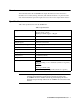
Overview This manual describes the 35-3010RKA-07 sample-draw detector. This manual also describes how to install, start up, maintain, and calibrate the detector. A parts list at the end of this manual lists replacement parts and accessories for the sample-draw detector. Specifications Table 1 lists specifications for the 35-3010RKA-07.
Description This section describes the components of the 35-3010RKA-07 sample-draw detector. The sample-draw detector consists of the housing, flow system, and detection system.
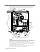
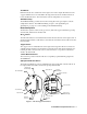
Flow System The sample-draw detector’s flow system consists of the INLET fitting, hydrophobic filter, charcoal filter, pump, flowmeter, bypass valve, status lights, pressure switch, flow blocks, and EXHAUST fitting (see Figure 1). Figure 2 illustrates how the gas sample moves through the flow system.
Charcoal Filter The charcoal filter is located above the LEL transmitter. It is held in place by a metal clip. The charcoal filter is placed after the H2S sensor and before the CO sensor (if one is installed) in the flow system. It scrubs out interfering gases which may cause the CO sensor to respond, such as H2S or certain hydrocarbons. It is included in this version of the sample draw detector in case a CO sensor is added in the field.
Flow Blocks Both flow blocks are located in the lower right corner of the sample-draw detector. The oxygen and H2S sensors are installed in the larger flow block. The smaller flow block houses the IR CH4 sensor. The flow blocks route the sampled air to each sensor. EXHAUST Fitting The EXHAUST fitting on the bottom of the housing allows the gas sample to exit the sample-draw detector. The EXHAUST fitting accepts 1/4 in. rigid tubing. See “Installation” on page 9 to connect tubing to the EXHAUST fitting.
LEL Transmitter The LEL transmitter is mounted to the left of the oxygen transmitter and above the main circuit board. It consists of the span pot, zero pot, one internally wired terminal strip, and the test points. Span/Zero Pots The span and zero pots are located at the bottom edge of the transmitter and are used for calibration.
signal. Since the CO sensor is replaced with a dummy plug in the 35-3010RKA-07 the CO sensor signal cable carries no signal in this version of the 35-3010RK.
NOTE: The sensors and transmitters are factory wired to the sensor/transmitter terminal strip. See “Wiring the Sample-Draw Detector” on page 10 for all wiring procedures related to the sample-draw detector. Amp 1 and Amp 2 Circuits These circuits are located to the left of the sensor/transmitter terminal strip. They each include test points, a zero pot, and a span pot. Amp 1 is on the left and is for the CO channel. Amp 2 is on the right and is for the H2S channel.
Installation This section describes procedures to mount the sample-draw gas detector in the monitoring environment and wire the sample-draw detector to power and an external device. Mounting the Sample-Draw Detector 1. Select the mounting site. Consider the following when you select the mounting site.
5. Repeat steps 3 and 4 for the remaining three mounting feet. 6. Position the sample-draw housing on a vertical surface at eye level (4 1/2 to 5 feet from the floor). 7. Insert 1/4 in. or 5/16 in. screws through the slots in the mounting feet to secure the housing to the mounting surface. Connecting the Sample Lines to the Sample-Draw Detector 1. Attach 1/4 in. O.D. rigid polypropylene or rigid Teflon sample tubing to the INLET fitting.
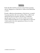
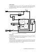
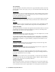
Sample Draw Housing Main Circuit Board Reset Switch Interconnect T erm inal Strip Oxygen (Controller Transmitter Terminals) + 4-20 (Feedback) 24 VDC 4/20 Feedback + 24 VDC - LEL (Controller Transmitter Terminals) H2S 4/20 Feedback (Controller Transmitter 24 VDC + Terminals) Figure 6: External (Field) Wiring, Sample-Draw Detector 35-3010RKA-07 Sample-Draw Detector • 11
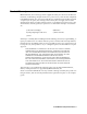
TP+ GND TS E N U M S T R I N SENSOR + FB 4 /20 2 4V 24V 4-20 ZERO RED WHT SPAN GRN BLK TP- BATT TP + + TP - POWER/ SIG P/N 57 -105 0R K REV.
Start Up This section describes procedures to start up the sample-draw detector and place the sample-draw detector into normal operation. Introducing Incoming Power 1. Complete the installation procedures described earlier in this manual. 2. Verify that the power wiring to the controller is correct and secure. See the controller operator’s manual. 3. Turn on or plug in the incoming power at the controller, then turn on the controller. 4. Verify that the Pilot light is on at the sample draw detector.
6. If necessary, use a small flat-blade screwdriver to adjust the zero pot until the voltmeter reading is 100 mV (± 2 mV). 7. Close the housing door. Operation Normal Operation During normal operation, the Pilot LED will be on and the flowmeter will indicate about 1.2 SCFH. The current gas readings will be indicated at the controller. See the controller’s operator’s manual for a description of the reading indications. Low Flow Alarm If the flowrate falls below 0.6 SCFH (±0.
Monthly This procedure describes a test to verify that the sample-draw detector responds properly to the target gases. Preparing for the response test CAUTION: This procedure may cause alarms at the controller. Take appropriate action to avoid this, such as entering the calibration mode at the controller. 1. Verify that the controller is reading 0 for the IR CH4 and H2S channels and 20.9 for the oxygen channel. If the reading is not 0 on the IR CH4 or H2S channels or 20.
• The sample-draw detector is malfunctioning. • The sensor or transmitter wiring is disconnected or misconnected. Recommended Action 1. At the sample-draw detector, set the correct flow rate with the bypass valve or flow adjust potentiometer. 2. If you cannot set the correct flow rate, check the sample lines for obstructions or kinks. 3. Verify that the sensor and transmitter wiring are correct and secure. “Wiring the Sample-Draw Detector” on page 10 describes detector wiring connections. 4.
Replacing Components of the Sample-Draw Detector This section includes procedures to replace the sensors, the hydrophobic filter, and the charcoal filter. Replacing the IR CH4 Sensor 1. Turn off or unplug incoming power. 2. Unscrew the four screws that hold the circuit board on the flow block. 3. Pull the circuit board off the flow block. 4. Unplug the infrared detector from the circuit board. 5. Plug the new detector into the circuit board. 6. Reinstall the circuit board to the flow block. 7.
9. Calibrate the replacement sensor as described in “Parts List” on page 23. Replacing the Hydrophobic Filter 1. Turn off or unplug power to the controller. 2. Locate the hydrophobic filter. It is just to the left of the main circuit board. 3. Grasp the hydrophobic filter and pull it out of its metal clamp. 4. Remove the rubber seals from each end of the hydrophobic filter and remove the filter. 5. Place the new hydrophobic filter in the same orientation as the one that was removed. 6.
and H2S sensors and every 6 months for the IR CH4 sensor in the sample draw detector. If an application is not very demanding, for example detection in a clean, temperature controlled environment, and calibration adjustments are minimal at calibration, then a calibration frequency of every 6 months for the oxygen and H2S sensors and every 12 months for the IR CH4 sensor is adequate for the sample draw detector.
2. Connect the calibration kit sample tubing to the regulator. 3. Connect the sample tubing from the regulator to the inlet line at or near the INLET fitting. 4. Allow the gas to flow for one minute. 5. Verify a voltmeter reading of 100 mV ± 2 mV at the LEL test points as described in the Preparing for Calibration section above. 6. If necessary, use a small flat-blade screwdriver to adjust the zero pot for the IR CH4 channel until the voltmeter reading is 100 mV ± 2 mV. 7.
Calibration, Oxygen Detector This section describes how to calibrate the oxygen detector in the sample-draw detector. It includes procedures to prepare for calibration, set the fresh air reading, set the zero reading, and return to normal operation. NOTE: This procedure describes calibration using a demand flow regulator, a zero air calibration cylinder, and a 4-gas calibration cylinder to set the zero reading.
8. For convenience, leave the regulator attached to the sample tubing. Setting the Fresh Air Reading CAUTION: This procedure may cause alarms at the controller. Take appropriate action to avoid this, such as entering the calibration mode at the controller. NOTE: If you can verify a fresh air environment, it is not necessary to use the zero air calibration cylinder to set the zero reading. 1. Screw the regulator into the zero air calibration cylinder. 2.
Parts List Table 4 lists replacement parts and accessories for the sample-draw gas detector.