35-3010RKA-08 Sample-Draw Detector Part Number: 71-0321RK Revision: P1 Released: 6/4/14 www.rkiinstruments.
WARNING Read and understand this instruction manual before operating detector. Improper use of the detector could result in bodily harm or death. Periodic calibration and maintenance of the detector is essential for proper operation and correct readings. Please calibrate and maintain this detector regularly! Frequency of calibration depends upon the type of use you have and the sensor types.
Product Warranty RKI Instruments, Inc. warrants gas alarm equipment sold by us to be free from defects in materials, workmanship, and performance for a period of one year from date of shipment from RKI Instruments, Inc. Any parts found defective within that period will be repaired or replaced, at our option, free of charge.
Table of Contents Overview . . . . . . . . . . . . . . . . . . . . . . . . . . . . . . . . . . . . . . . . . . . . . . . . . . . . . . . . . . . . . . . . . . . 1 Specifications. . . . . . . . . . . . . . . . . . . . . . . . . . . . . . . . . . . . . . . . . . . . . . . . . . . . . . . . . . . . . . . . 1 Description . . . . . . . . . . . . . . . . . . . . . . . . . . . . . . . . . . . . . . . . . . . . . . . . . . . . . . . . . . . . . . . . . . 2 Housing . . . . . . . . . . . . . . . . . . . . . . . . . .
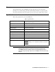
Overview This manual describes the 35-3010RKA-08 sample-draw detector. This manual also describes how to install, start up, maintain, and calibrate the detector. A parts list at the end of this manual lists replacement parts and accessories for the sample-draw detector. Specifications Table 1 lists specifications for the 35-3010RKA-08.
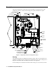
Description This section describes the components of the 35-3010RKA-08 sample-draw detector. The sample-draw detector consists of the housing, flow system, and detection system.
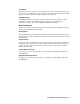
mounting feet to install the housing to a vertical surface. Use the two conduit hubs on the bottom of the housing to make wiring connections. An aluminum subpanel is mounted to the interior of the housing. The sample-draw detector’s internal components are mounted to the subpanel.
Charcoal Filter The charcoal filter is located above the LEL transmitter. It is held in place by a metal clip. The charcoal filter is placed after the H2S sensor (if one is installed) and before the CO sensor (if one is installed) in the flow system. It scrubs out interfering gases which may cause the CO sensor to respond, such as H2S or certain hydrocarbons. It is included in this version of the sample draw detector in case a CO sensor is added in the field.
Flow Blocks Both flow blocks are located in the lower right corner of the sample-draw detector. The oxygen sensor is installed in the larger flow block. The smaller flow block houses the IR CH4 sensor. The flow blocks route the sampled air to each sensor. EXHAUST Fitting The EXHAUST fitting on the bottom of the housing allows the gas sample to exit the sample-draw detector. The EXHAUST fitting accepts 1/4 in. rigid tubing. See “Installation” on page 10 to connect tubing to the EXHAUST fitting.
LEL Transmitter The LEL transmitter is mounted to the left of the oxygen transmitter and above the main circuit board. It consists of the span pot, zero pot, one internally wired terminal strip, and the test points. Interconnect Terminal Strip POWER/SIG P/N 57-1050RK REV.
Oxygen Transmitter The oxygen transmitter is mounted to the right of the LEL transmitter and above the main circuit board. The amplifier includes the amplifier type selector, two internally wired terminal strips, span pot, zero pot, and test points.
Preamp Circuit Board The preamp circuit is used to connect the CO and H2S sensors to the main circuit board and to secure the sensors in the flow block. Two cables mate to the main circuit board: the one on the left is for the CO sensor signal and the one on the right is for the H2S sensor signal. Since the CO and H2S sensors are replaced with a dummy plug in the 35-3010RKA08 the CO and H2S sensor signal cables carry no signal in this version of the 35-3010RK.
Sensor/Transmitter Terminal Strip The sensor/transmitter terminal strip is the sixteen-point terminal strip near the right edge of the circuit board. Use the transmitter terminal strip to connect sensors or transmitters to the main circuit board. NOTE: The sensors and transmitters are factory wired to the sensor/transmitter terminal strip. See “Wiring the Sample-Draw Detector” on page 11 for all wiring procedures related to the sample-draw detector.
Installation This section describes procedures to mount the sample-draw gas detector in the monitoring environment and wire the sample-draw detector to power and an external device. Mounting the Sample-Draw Detector 1. Select the mounting site. Consider the following when you select the mounting site.
9. Tighten the screw that secures the mounting foot to the housing. 10. Repeat steps 3 and 4 for the remaining three mounting feet. 11. Position the sample-draw housing on a vertical surface at eye level (4 1/2 to 5 feet from the floor). 12. Insert 1/4 in. or 5/16 in. screws through the slots in the mounting feet to secure the housing to the mounting surface. Connecting the Sample Lines to the Sample-Draw Detector 1. Attach 1/4 in. O.D.
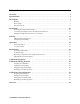
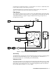
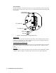
Sample Draw Housing Main Circuit Board Reset S witch Interconnect Terminal Strip Ox ygen (Controller Tra nsmitter Te rminals) + 4-2 0 ( Fe ed ba ck) 24 VD C 4/20 F eedback + 24 VD C - Figure 7: External (Field) Wiring, Sample-Draw Detector 12 • 35-3010RKA-08 Sample-Draw Detector LEL (C on tro lle r Transmitt er Te rminals)
T P+ GND I NSTR UME NTS FB 4 /2 0 24V 24 V 4- 20 ZER O RE D S E NSOR B AT T + TP- P OW E R /SIG R E V.
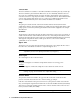
Start Up This section describes procedures to start up the sample-draw detector and place the sample-draw detector into normal operation. Introducing Incoming Power 1. Complete the installation procedures described earlier in this manual. 2. Verify that the power wiring to the controller is correct and secure. See the controller operator’s manual. 3. Turn on or plug in the incoming power at the controller, then turn on the controller. 4. Verify that the Pilot light is on at the sample draw detector.
8. If necessary, use a small flat-blade screwdriver to adjust the oxygen transmitter’s zero pot until the voltmeter reading is 434 mV (± 2 mV). 9. Close the housing door. Operation Normal Operation During normal operation, the Pilot LED will be on and the flowmeter will indicate about 1.2 SCFH. The current gas readings will be indicated at the controller. See the controller’s operator’s manual for a description of the reading indications. Low Flow Alarm If the flowrate falls below 0.6 SCFH (±0.
Monthly This procedure describes a test to verify that the sample-draw detector responds properly to the target gases. Preparing for the response test CAUTION: This procedure may cause alarms at the controller. Take appropriate action to avoid this, such as entering the calibration mode at the controller. 1. Verify that the controller is reading 0 %LEL for the IR CH4 channel and 20.9 for the oxygen channel. If the reading is not 0 %LEL on the IR CH4 channel or 20.
Fail Condition Symptoms • The sample-draw detector’s Fail light is on. • The controller is operating properly but indicates a reading well below zero on one or more channels. Probable Causes • The sample-draw detector’s flow rate is too low because of an obstructed sample line, failed pump, etc. • The sample-draw detector is malfunctioning. • The sensor or transmitter wiring is disconnected or misconnected. Recommended Action 1.
4. If the calibration/response difficulties continue, replace the sensor as described later in this section. 5. If the calibration/response difficulties continue, contact RKI Instruments, Inc. for further instruction. Replacing Components of the Sample-Draw Detector This section includes procedures to replace the sensors, the hydrophobic filter, and the charcoal filter. Replacing the IR CH4 Sensor 1. Turn off or unplug incoming power. 2.
Replacing the Charcoal Filter NOTE: The charcoal filter does not normally need to be replaced in the 35-3010RKA-08 because it does not include a CO sensor. 1. Turn off or unplug power to the controller. 2. Locate the charcoal filter. It is located along the upper edge of the detector housing. 3. Grasp the charcoal filter and pull it out of its metal clamp. 4. Remove the rubber seals from each end of the charcoal filter and remove the filter. 5.
Calibration, IR CH4 Detector This section describes how to calibrate the IR CH4 sensor in the sample draw detector. It includes procedures to prepare for calibration, set the zero reading, set the response reading, and return to normal operation. NOTE: This procedure describes calibration using a demand flow regulator, a zero air calibration cylinder, and a methane calibration cylinder. Preparing for Calibration CAUTION: This procedure may cause alarms at the controller.
2. Connect the sample tubing from the regulator to the inlet line at or near the sampledraw detector’s INLET fitting. 3. Allow the calibration gas to flow for one minute. 4. Check the mV output on the LEL transmitter test points and verify that the reading matches the response reading (±2 mV) you determined earlier. 5. If necessary, use the span pot on the LEL transmitter to adjust the reading to match the correct response reading. 6.
draw detector’s INLET fitting. 4. Allow the sample-draw detector to respond to the calibrating sample for approximately 1 minute. 5. After one minute, check the mV output on the oxygen transmitter test points and verify a reading of 100 mV (±2 mV). 6. If necessary, use the span pot on the transmitter to adjust the reading to 100 mV (± 2 mV) 7. Disconnect the sample tubing from the inlet line. 8. Unscrew the regulator from the 100% nitrogen calibration cylinder. 9.
Parts List Table 4 lists replacement parts and accessories for the sample-draw gas detector.