61-1000RK-05 Combustible Gas Detector Operator’s Manual Part Number: 71-0087RK Revision: E Released: 1/31/13 www.rkiinstruments.
WARNING Read and understand this instruction manual before operating detector. Improper use of the detector could result in bodily harm or death. Periodic calibration and maintenance of the detector is essential for proper operation and correct readings. Please calibrate and maintain this detector regularly! Frequency of calibration depends upon the type of use you have and the sensor types.
Product Warranty RKI Instruments, Inc. warranties gas alarm equipment sold by us to be free from defects in materials, workmanship, and performance for a period of one year from date of shipment from RKI Instruments, Inc. Any parts found defective within that period will be repaired or replaced, at our option, free of charge.
Table of Contents Overview . . . . . . . . . . . . . . . . . . . . . . . . . . . . . . . . . . . . . . . . . . . . . . . . . . . . . . . . . . . . . . . . . . . 1 Specifications. . . . . . . . . . . . . . . . . . . . . . . . . . . . . . . . . . . . . . . . . . . . . . . . . . . . . . . . . . . . . . . . 1 Description . . . . . . . . . . . . . . . . . . . . . . . . . . . . . . . . . . . . . . . . . . . . . . . . . . . . . . . . . . . . . . . . . . 2 61-0140RK-05 Combustible Gas Detector . . . . . . . . . . .
Overview This manual describes the 61-1000RK-05 combustible gas detector (internal amplifier type). This manual also describes how to install, start up, maintain, and calibrate the detector when it is used with a gas monitoring controller. A parts list at the end of this manual lists replacement parts and accessories for the combustible gas detector. The 61-1000RK-05 combustible gas detector includes the 61-0140RK-05 combustible gas detector and a junction box.
Description This section describes the components of the 61-0140RK-05 and 61-1000RK-05 detectors. The 61-1000RK-05 includes the 61-0140RK-05 combustible gas detector and a junction box. A four point terminal strip is provided inside the junction box for detector connections. The 61-0140RK-05 does not include a junction box.
process. A cover on the front of the junction box allows access to the interior of the junction box. Installation This section describes procedures to mount the combustible gas detector in the monitoring environment and wire the detector to a controller. NOTE: The 61-0140RK-05 detector retains its explosion proof classification only when installed in the explosion proof junction box. The detector is not explosion proof if installed in a controller conduit hub. Mounting the Combustible Gas Detector 1.
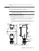
2. At the mounting site you select, hang or mount the junction box with the detector facing down (see Figure 2). Wiring the Combustible Gas Detector to a Controller WARNING: Always verify that the power to the controller is off before you make wiring connections. 1. Turn off the controller. 2. Turn off power to the controller. 3. If the detector is mounted remotely from a controller using the junction box, proceed to step 4.
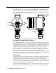
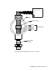
Controller LEL Detector Terminals RED WH ITE GREEN BLACK J-Box Terminal Stri p Black Green Detector Wires Whi te Red Combustible Detector Figure 3: Wiring the Combustible Gas Detector to a Controller 61-1000RK-05 Combustible Gas Detector • 5
Start Up This section describes procedures to start up the combustible gas detector and place the detector into normal operation. Introducing Incoming Power 1. Complete the installation procedures described earlier in this manual. 2. Verify that the power wiring to the controller is correct and secure. Refer to the controller operator’s manual. 3. Turn on power to the controller. 4. Turn on the controller. 5. Verify that the controller is on and operating properly.
Maintenance This section describes maintenance procedures. It includes preventive maintenance, troubleshooting, and component replacement procedures. Preventive Maintenance This section describes a preventive maintenance schedule to ensure the optimum performance of the combustible gas detector. It includes daily, monthly, and quarterly procedures. Daily Verify a display reading of 0% LEL at the controller. Investigate significant changes in the reading.
3. Verify that the reading is within ± 20% of the gas concentration. NOTE: If the readings are not within ± 20% of the gas concentration, calibrate the detector as described in the Calibration section of this manual. 4. Turn the regulator knob clockwise to close the regulator. 5. Unscrew the regulator from the calibration cylinder. 6. Unscrew the calibration cup from the detector. 7. When the display reading falls below the alarm setpoints, return the controller to normal operation. 8.
Replacing the Combustible Detector 1. Turn off the controller. 2. Turn off power to the controller. 3. If the detector is installed directly on a controller, open the controller door. If the detector is installed remotely from a controller in a junction box, remove the junction box cover. 4. If the detector is installed directly on a controller, disconnect the detector leads from the detector terminal strip in the controller. Note the position of the color-coded leads as you remove them.
adequate. If an application is very demanding, for example if combustible gas is present often and in significant concentrations or the environment is not well controlled, then more frequent calibration than every 3 months may be necessary. If potential catalyst poisons are known or likely to be present, more frequent calibration than every 3 months will be necessary. Calibration This section describes how to calibrate the combustible gas detector.
Setting the Response Reading 1. Follow the directions in the controller’s operator’s manual for setting the response reading (span). 2. When the directions call for exposing the detector to gas, turn the regulator’s on/off knob counterclockwise to open it. 3. Allow the gas to flow for one minute before continuing with the directions. 4. After setting the response reading, turn the regulator’s on/off knob clockwise to close it. 5. Unscrew the regulator from the cylinder.