61-1000RKSS-05 Combustible Gas Detector Operator’s Manual Part Number: 71-0199RK Revision: A Released: 1/31/13 www.rkiinstruments.
WARNING Read and understand this instruction manual before operating detector. Improper use of the detector could result in bodily harm or death. Periodic calibration and maintenance of the detector is essential for proper operation and correct readings. Please calibrate and maintain this detector regularly! Frequency of calibration depends upon the type of use you have and the sensor types.
Product Warranty RKI Instruments, Inc. warranties gas alarm equipment sold by us to be free from defects in materials, workmanship, and performance for a period of one year from date of shipment from RKI Instruments, Inc. Any parts found defective within that period will be repaired or replaced, at our option, free of charge.
Table of Contents Overview . . . . . . . . . . . . . . . . . . . . . . . . . . . . . . . . . . . . . . . . . . . . . . . . . . . . . . . . . . . . . . . . . . . 1 Specifications. . . . . . . . . . . . . . . . . . . . . . . . . . . . . . . . . . . . . . . . . . . . . . . . . . . . . . . . . . . . . . . . 1 Description . . . . . . . . . . . . . . . . . . . . . . . . . . . . . . . . . . . . . . . . . . . . . . . . . . . . . . . . . . . . . . . . . . 2 Combustible Gas Detector. . . . . . . . . . . . . . . . . .
Overview This manual describes the 61-1000RKSS-05 combustible gas detector (internal amplifier type). This manual also describes how to install, start up, maintain, and calibrate the detector when it is used with a gas monitoring controller. A parts list at the end of this manual lists replacement parts and accessories for the combustible gas detector. Specifications WARNING: Do not use this product in a manner not specified in this instruction manual.
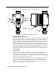
Description This section describes the components of the 61-1000RKSS-05 detector. Green Red Black White Locking Set Screw J-Box Figure 1: 61-1000RKSS-05 Component Location Combustible Gas Detector The combustible gas detector is a catalytic type detector that produces an electrical output that corresponds to the detection range. It is packaged in a 1/2 inch NPT nipple with a sintered metal flame arrestor on one end allowing ambient air to diffuse into the detector.
Installation This section describes procedures to mount the combustible gas detector in the monitoring environment and wire the detector to a controller. Mounting the Combustible Gas Detector 1. Select a mounting site that is representative of the monitoring environment. Consider the following when you select the mounting site. • Select a site where the detector is not likely to be bumped or disturbed. Make sure there is sufficient room to perform start-up, maintenance, and calibration procedures.
Wiring the Combustible Gas Detector to a Controller WARNING: Always verify that the power to the controller is off before you make wiring connections. 1. Turn off the controller. 2. Turn off power to the controller. 3. Remove the junction box cover. 4. Guide a four-conductor, shielded cable or four wires in conduit through the unused conduit hub of the junction box.
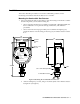
Controller LEL Detector T erminals RED WHITE GREEN BLACK J-Box Terminal Strip Black Green Detector Wires White Red Combustible Detector Figure 3: Wiring the Combustible Gas Detector to a Controller 61-1000RKSS-05 Combustible Gas Detector• 5
Start Up This section describes procedures to start up the combustible gas detector and place the detector into normal operation. Introducing Incoming Power 1. Complete the installation procedures described earlier in this manual. 2. Verify that the power wiring to the controller is correct and secure. Refer to the controller operator’s manual. 3. Turn on power to the controller. 4. Turn on the controller. 5. Verify that the controller is on and operating properly.
9. When zeroing operation is complete, turn the regulator’s on/off knob clockwise to close it. 10. Unscrew the calibration cup from the detector. 11. Unscrew the regulator from the zero air calibration cylinder. For convenience, leave the sample tubing connected to the regulator and the calibration cup. 12. Store the components of the calibration kit in a safe and convenient place. Maintenance This section describes maintenance procedures.
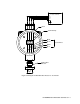
4. Screw the calibration cup over the bottom of the detector. 5. Use the calibration kit sample tubing to connect the regulator to the calibration cup. Performing the response test 1. Turn the regulator’s on/off knob counterclockwise to open the regulator. Gas will begin to flow. 2. Allow the gas to flow for one minute. 3. Verify that the reading is within ± 20% of the gas concentration.
Table 2:Troubleshooting the Combustible Gas Detector (Continued) Condition Slow or No Response/ Difficult or Unable to Calibrate Symptom(s) Probable Causes • Detector responds slowly or does not respond to response test. • Unable to accurately set the zero or response reading during calibration. • Detector requires frequent calibration. • The calibration cylinder is low, out-dated, or defective. • The calibration gas is not an appropriate concentration. • The detector is malfunctioning.
Calibration Frequency Although there is no particular calibration frequency that is correct for all applications, a calibration frequency of every 3 to 6 months is adequate for most combustible gas detector applications. Unless experience in a particular application dictates otherwise, RKI Instruments, Inc. recommends a calibration frequency of every 3 months.
Setting the Zero Reading NOTE If you can verify that the combustible gas transmitter is in a fresh air environment, you do not need to apply zero air to the detector before adjusting the zero reading. 1. Screw the regulator into the zero air calibration cylinder. 2. Use the sample tubing to connect the regulator to the calibration cup. 3. Perform a zeroing operation at the controller. See the controller operator’s manual for directions. 4.
Parts List Table 3 lists replacement parts and accessories for the 61-1000RKSS-05 combustible gas detector.