61-1007RKSS CO2 Detector Operator’s Manual Part Number: 71-0297RK Revision: 0 Released: 7/18/14 www.rkiinstruments.
WARNING Read and understand this instruction manual before operating detector. Improper use of the detector could result in bodily harm or death. Periodic calibration and maintenance of the detector is essential for proper operation and correct readings. Please calibrate and maintain this detector regularly! Frequency of calibration depends upon the type of use you have and the sensor types.
Product Warranty RKI Instruments, Inc. warrants gas alarm equipment sold by us to be free from defects in materials, workmanship, and performance for a period of one year from date of shipment from RKI Instruments, Inc. Any parts found defective within that period will be repaired or replaced, at our option, free of charge.
Table of Contents Overview . . . . . . . . . . . . . . . . . . . . . . . . . . . . . . . . . . . . . . . . . . . . . . . . . . . . . . . . . . . . . . . . . . . 1 Specifications. . . . . . . . . . . . . . . . . . . . . . . . . . . . . . . . . . . . . . . . . . . . . . . . . . . . . . . . . . . . . . . . 1 Description . . . . . . . . . . . . . . . . . . . . . . . . . . . . . . . . . . . . . . . . . . . . . . . . . . . . . . . . . . . . . . . . . . 2 IR CO2 Detector. . . . . . . . . . . . . . . . . . . . . .
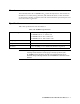
Overview This manual describes the 61-1007RKSS CO2 (carbon dioxide) detector. This manual also describes how to install, start up, maintain, and calibrate the detector when used with a gas monitoring controller. A parts list at the end of this manual lists replacement parts and accessories for the CO2 detector. Specifications Table 1 lists specifications for the CO2 detector.
Description The 61-1007RKSS CO2 detector has four versions, the 61-1007RKSS-02 which has a detection range of 0 - 5,000 ppm, the 61-1007RKSS-03 which has a detection range of 0 - 5% volume, the 61-1007RKSS-05 which has a detection range of 0 - 50% volume, and the 61-1007RKSS-10 which has a detection range of 0 - 100% volume. The detector is an infrared type of detector. This section describes the components of the 61-1007RKSS detector. The 61-1007RKSS includes the detector and a junction box.
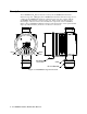
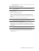
Infrared CO2 Detector The CO2 detector consists of the detector housing body, detector housing cap, cap gasket, and the plug-in sensor. Detector Housing Body Cap Gasket Plug-In IR CO2 Sensor Detector Housing Cap Hydrophobic Membrane Figure 2: CO2 Detector Component Location Detector Housing Body The detector housing body protects the electronic components within the housing.
connect the wiring from the detector to a controller. An O-ring seals the interface between the junction box cover and the junction box base. The terminal block within the junction box facilitates the wiring process. A cover on the front of the junction box allows access to the interior of the junction box. A locking set screw on the junction box cover allows you to secure the junction box cover and prevent it from being removed.
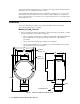
2. At the mounting site you select, hang or mount the junction box with the detector facing down (see Figure 3). Wiring the CO2 Detector to a Controller WARNING: Always verify that the power to the controller is off before you make wiring connections. 1. Turn off the controller. 2. Turn off or unplug power to the controller. 3. Remove the cover from the junction box. 4. Guide a four-conductor, shielded cable or four wires in conduit through the top conduit hub of the junction box.
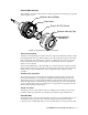
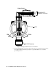
Cable Shield RED WHITE GREEN BLACK Controller LEL Detector Terminals J-Box Red Black Green White IR CO2 Detector Figure 4: Wiring the CO2 Detector to a Controller 9. If using shielded cable, connect the cable’s drain wire to an available chassis ground at the controller. RKI controllers typically have a ground stud that is a convenient grounding location.
Start Up This section describes procedures to start up the CO2 detector and place the detector into normal operation. Introducing Incoming Power 1. Complete the installation procedures described earlier in this manual. 2. Verify that the power wiring to the controller is correct and secure. Refer to the controller operator’s manual. 3. Turn on or plug in power to the controller, then turn on the controller. 4. Verify that the controller is on and operating properly.
Maintenance This section describes maintenance procedures. It includes preventive maintenance, troubleshooting, and component replacement procedures. Preventive Maintenance This section describes a preventive maintenance schedule to ensure the optimum performance of the CO2 detector. It includes daily, monthly, and biannual procedures. Daily Verify a display reading at the controller of the background concentration of CO2. Typical background concentrations of CO2 vary from about 300 to 600 ppm (0.03 to 0.
NOTE: If the reading is not within ± 20% of the gas concentration, calibrate the detector as described in “Calibration” on page 12. 9. Turn the on/off knob clockwise to close the regulator. 10. Unscrew the regulator from the calibration cylinder and remove the sample tubing from the regulator. 11. Unscrew the calibration cup from the detector. You may leave the sample tubing connected to the calibration cup for convenience. 12.
Table 2:Troubleshooting the CO2 Detector (Continued) Condition Slow or No Response/ Difficult or Unable to Calibrate Symptom(s) Probable Causes Recommended Action • Detector responds slowly or does not respond to response test. • Unable to accurately set the zero or response reading during calibration. • Detector requires frequent calibration. • The calibration cylinder is low, out-dated, or defective. • The regulator flow rate is not 0.5 LPM. • The detector is malfunctioning. 1.
lose the cap gasket. 4. Unplug and remove the plug-in IR CO2 sensor. 5. Carefully plug the replacement sensor into the socket pattern that is located in the detector housing. 6. Make sure the cap gasket is in place and screw the detector housing cap back onto the detector housing body. 7. Turn on power to the controller. 8. Turn on the controller and place it into normal operation. CAUTION: Allow the replacement sensor to warm up for 5 minutes before you continue with the next step. 9.
Calibration Frequency Although there is no particular calibration frequency that is correct for all applications, a calibration frequency of every 6 months is adequate for most infrared CO2 detector applications. Unless experience in a particular application dictates otherwise, RKI Instruments, Inc. recommends a calibration frequency of every 6 months for the infrared CO2 detector.
allow the gas to flow to the detector for 1 minute. 3. Turn the regulator’s on/off knob clockwise to close the regulator. 4. Set the zero reading according to the controller’s operator’s manual. 5. Unscrew the 100% nitrogen cylinder from the regulator. Setting the Response Reading 1. Follow the directions in the controller’s operator’s manual for setting the response reading (span). 2.
Parts List Table 3 lists replacement parts and accessories for the 61-1007RKSS CO2 detector.