65-2300RK/65-2301RK Toxic Detector Operator’s Manual Part Number: 71-0146RK Revision: C Released: 2/15/13 www.rkiinstruments.
WARNING Read and understand this instruction manual before operating detector. Improper use of the detector could result in bodily harm or death. Periodic calibration and maintenance of the detector is essential for proper operation and correct readings. Please calibrate and maintain this detector regularly! Frequency of calibration depends upon the type of use you have and the sensor types.
Product Warranty RKI Instruments, Inc. warrants gas alarm equipment sold by us to be free from defects in materials, workmanship, and performance for a period of one year from date of shipment from RKI Instruments, Inc. Any parts found defective within that period will be repaired or replaced, at our option, free of charge.
Table of Contents Overview . . . . . . . . . . . . . . . . . . . . . . . . . . . . . . . . . . . . . . . . . . . . . . . . . . . . . . . . . . . . . . . . . . . 1 Specifications. . . . . . . . . . . . . . . . . . . . . . . . . . . . . . . . . . . . . . . . . . . . . . . . . . . . . . . . . . . . . . . . 1 Description . . . . . . . . . . . . . . . . . . . . . . . . . . . . . . . . . . . . . . . . . . . . . . . . . . . . . . . . . . . . . . . . . . 3 65-2300RK Toxic Detector . . . . . . . . . . . . . . . . .
Overview This manual describes the 65-2301RK toxic detector. This manual also describes how to install, start up, maintain, and calibrate the toxic detector when used with a gas monitoring controller. A parts list at the end of this manual lists replacement parts and accessories for the toxic detector. The 65-2301RK toxic detector includes the 65-2300RK toxic detector and a junction box.
Table 1: Specifications Operating Temperature & Humidity • 14°F to 104°F (-10°C to 40°C) • 20% to 90% Relative Humidity WARNING: When using the 65-2300RK/65-2301RK, you must follow the instructions and warnings in this manual to assure proper and safe operation of the 65-2300RK/65-2301RK and to minimize the risk of personal injury. Be sure to maintain and periodically calibrate the 65-2300RK/65-2301RK as described in this manual.
Description This section describes the components of the 65-2300RK and 65-2301RK. The 65-2301RK includes the 65-2300RK toxic detector and a junction box. The 65-2300RK does not include a junction box. Figure 1 below shows the components of the 65-2301RK.
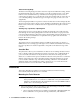
Detector Housing Body The detector housing body protects the electronic components within the housing. Use the mounting threads at the top of the housing to screw the toxic detector into a 3/4” NPT hub. Two wires extend from the top of the detector housing body. Use these wires to connect the toxic detector to a controller. One of the wires is black and one of the wires is color coded depending on the detector type. See Figure 4 on page 6 for the color code assignments.
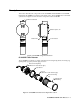
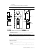
procedures. • Select a site where the target gas is likely to be found first. NOTE: If your application does not require a specific mounting site, mount the detector at approximately breathing level. 2.70 .75 3/4 NPT Conduit Hub 7.30 + .25 0.38 3/4" NPT 3.65 Rubber Spacer, 3X .75 9.60 Max 4.78 Junction Box Toxic Detector Ø 1.50 65-2300RK 65-2301RK Figure 3: Outline & Mounting Dimensions, 65-2300RK & 65-2301RK 2.
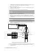
and black wires to the appropriate controller detector terminals (see Figure 4 for the color coding of the non-black wire) and skip to the Startup Section. 4. Remove the junction box cover. 5. Guide a two-conductor, shielded cable or two wires in conduit through the unused conduit hub of the junction box. 6. Connect the two wires to the detector using the terminal block. CAUTION: If using shielded cable, leave the drain wire insulated and disconnected at the detector.
. Reinstall the junction box cover. Start Up This section describes procedures to start up the toxic detector and place the detector into normal operation. Introducing Incoming Power 1. Complete the installation procedures described earlier in this manual. 2. Verify that the power wiring to the controller is correct and secure. Refer to the controller operator’s manual. 3. Turn on or plug in the incoming power, then turn on the controller. 4.
calibration gas, sample tubing, and a fixed flow regulator with an on/off knob. See Table 2 on page 12 to determine the correct calibration cup and regulator for the required flowrate for your detector. WARNING: Failure to use the recommended calibration cup and calibration gas flow rate will result in an inaccurate reading. NOTE: Performing a response test on the toxic detector may cause alarms.
Troubleshooting The troubleshooting guide describes symptoms, probable causes, and recommended action for problems you may encounter with the toxic detector. NOTE: This troubleshooting guide describes detector problems only. See the controller operator’s manual for problems you may encounter with the controller. Fail Condition Symptoms • The controller indicates a fail condition. Probable causes • The detector wiring is disconnected or misconnected.
Recommended action 1. Verify that the calibration cylinder contains an adequate supply of a fresh test sample. 2. Confirm that you are using the correct calibration cup and regulator for your detector type. See Table 2 on page 12 for a list of the required calibration cups and regulators. 3. Check the plug-in sensor face and remove any particulate contamination if necessary. 4. If the calibration/response difficulties continue, replace the plug-in sensor as described later in this section. 5.
Replacing the Toxic Detector NOTE: In most cases, it is only necessary to replace the plug-in sensor. 1. Turn off the controller. 2. Turn off or unplug incoming power to the controller. 3. If the detector is installed directly on a controller, open the controller door. If the detector is installed remotely from a controller in a junction box, remove the junction box cover. 4.
If an application is not very demanding, for example detection in a clean, temperature controlled environment where toxic gas is not normally present, and calibration adjustments are minimal at calibration, then a calibration frequency of every 6 months is adequate. If an application is very demanding, for example if the environment is not well controlled or if toxic gas is often present, then more frequent calibration than every 3 months may be necessary.
3. Screw the regulator into the zero air calibration cylinder. 4. Use the sample tubing to connect the regulator to the calibration cup. Make sure to connect the tube to the inlet side of the calibration cup if using the 81-1138RK calibration cup which is marked on the outside bottom to show the required flow direction through the cup. NOTE 5.
NOTE: If you do not allow the gas reading to decrease below the alarm points, then unwanted alarms may occur. 9. Verify that the controller display reading decreases and stabilizes at 0 ppm. 10. Store the components of the calibration kit in a safe and convenient place. Parts List Table 3 lists replacement parts and accessories for the toxic detector.
Table 3: Parts List Part Number Description 81-0190RK-02 Calibration cylinder, 5 ppm Cl2 in nitrogen, 58 liter 81-0190RK-04 Calibration cylinder, 5 ppm Cl2 in nitrogen, 34 liter 81-0192RK-02 Calibration cylinder, 2 ppm Cl2 in nitrogen, 58 liter, aluminum 81-0192RK-04 Calibration cylinder, 2 ppm Cl2 in nitrogen, 34 liter aluminum 81-0196RK-02 Calibration cylinder, 10 ppm HCN in nitrogen, 58 liter aluminum 81-0196RK-04 Calibration cylinder, 10 ppm HCN in nitrogen, 34 liter aluminum 81-1050RK Re
Table 3: Parts List Part Number Description ESM-01DH-PH3 ESM-01 plug-in sensor, 0 - 1.00 ppm phosphine ESM-01R-D-NH3 ESM-01 plug-in sensor, 0 - 75.0 ppm ammonia, diffusion type only ESM-K01-D-CL2 ESM-01 plug-in sensor, 0 - 3.00 ppm chlorine, diffusion type only ESM-K01D-CL2-10 ESM-01 plug in sensor, 0 - 10.