65-2331RK Hydrogen Sulfide Transmitter Operator’s Manual Part Number: 71-0176RK Revision: A Released: 7/18/14 RKI Instruments, Inc. www.rkiinstruments.
WARNING Read and understand this instruction manual before operating detector. Improper use of the detector could result in bodily harm or death. Periodic calibration and maintenance of the detector is essential for proper operation and correct readings. Please calibrate and maintain this detector regularly! Frequency of calibration depends upon the type of use you have and the sensor types.
Product Warranty RKI Instruments, Inc. warrants gas alarm equipment sold by us to be free from defects in materials, workmanship, and performance for a period of one year from date of shipment from RKI Instruments, Inc. Any parts found defective within that period will be repaired or replaced, at our option, free of charge.
Table of Contents Overview . . . . . . . . . . . . . . . . . . . . . . . . . . . . . . . . . . . . . . . . . . . . . . . . . . . . . . . . . . . . . . . . . . . 1 Specifications. . . . . . . . . . . . . . . . . . . . . . . . . . . . . . . . . . . . . . . . . . . . . . . . . . . . . . . . . . . . . . . . 1 Description . . . . . . . . . . . . . . . . . . . . . . . . . . . . . . . . . . . . . . . . . . . . . . . . . . . . . . . . . . . . . . . . . . 2 H2S Detector . . . . . . . . . . . . . . . . . . . . . . .
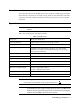
Overview This manual describes the 65-2331RK explosion-proof hydrogen sulfide (H2S) transmitter. This manual also describes how to install, start up, maintain, and calibrate the transmitter. A parts list at the end of this manual lists replacement parts and accessories for the H2S transmitter. Specifications WARNING: Do not use this product in a manner not specified in this instruction manual. Table 1 lists specifications for the H2S transmitter.
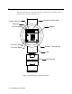
Description This section describes the components of the H2S transmitter. The transmitter consists of the H2S detector, amplifier, and junction box.
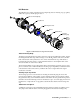
H2S Detector The H2S detector consists of the detector housing body, detector housing cap, cap gasket, rubber boot, spacer, and the plug-in sensor. Detector Housing Body Cap Gasket H2S Plug-in Sensor Spacer Rubber Boot Detector Housing Cap Flame Arrestor Guard Figure 2: H2S Detector Component Location Detector Housing Body The detector housing body protects the electronic components within the housing.
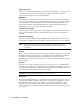
Plug-In H2S Sensor The sensor is secured within the detector assembly by the housing cap. Through a series of chemical and electrical reactions, the sensor produces an electrical output that corresponds to the detection range of the transmitter. Amplifier The amplifier converts the electrical output from the sensor to a 4 to 20 mA signal that corresponds to the detection range and transmits the signal to a gas monitoring controller.
Junction Box Use the junction box to install the H2S transmitter at a mounting site that is remote from the controller. The junction box protects the amplifier and wiring connections made to the amplifier. Use the top 3/4’’ conduit hub to connect wiring from the amplifier to the controller. Use the cover on the front of the junction box to access the interior of the junction box.
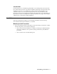
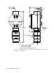
3.10 .75 3/4 NPT Female .38 3.65 Rubber Spacers 3X 8.18 Max J-Box H2S Detector 1 1/2-20 Thread for Calibration Cup Figure 3: Mounting the H2S Transmitter 2. At the monitoring site you select, hang or mount the junction box with the detector facing down (see Figure 3).
Wiring the H2S Transmitter to a Controller WARNING: Always verify that power to the controller is OFF before you make wiring connections. 1. Turn off the controller. 2. Turn off power to the controller. 3. Remove the junction box cover. 4. The detector leads are factory wired. Verify that the detector leads are wired to the amplifier’s detector terminal strip as shown in Figure 4. 5.
11. Connect the wires to the applicable detector/transmitter terminal strip at the controller as shown in Figure 4. Controller Detector/Transmitter Terminals, Typical Designations S + Cable Shield S SIG/P WR TOXIC OXY SPAN ZERO Controller J-Box Black Red H2S Detector Figure 4: Wiring the H2S Transmitter to a Controller 12. If shielded cable is used, connect the cable’s drain wire to an available chassis (earth) ground at the controller.
3. Turn on power to the controller. 4. Turn on the controller. 5. Verify that the controller is on and operating properly. Refer to the controller operator’s manual. CAUTION: Allow the transmitter to warm up for 5 minutes before you continue with the next section, “Setting the Zero Signal”. Setting the Zero Signal WARNING: Do not remove the detector housing cap or junction box cover while the circuits are energized unless the area is determined to be non-hazardous.
Maintenance This section describes maintenance procedures. It includes preventive maintenance, troubleshooting, and component replacement procedures. Preventive Maintenance This section describes a preventive maintenance schedule to ensure the optimum performance of the H2S transmitter. It includes daily, monthly, and quarterly procedures. Daily Verify a display reading of 0 ppm H2S at the controller. Investigate significant changes in the display reading.
Performing the response test 1. Turn the regulator’s on/off knob counterclockwise to open the regulator. Gas will begin to flow. 2. Allow the gas to flow for two minutes, then verify that the reading is within ± 20% of the response reading you determined earlier. NOTE: If the readings are not within ± 20% of the correct response reading, calibrate the affected transmitter(s) as described in the “Calibration” on page 15. 3. Turn the regulator’s on/off knob clockwise to close the regulator. 4.
Table 2: Troubleshooting H2S Transmitter Condition Symptom(s) Probable Causes Recommended Action Fail Condition • Controller indicates a fail condition. • The transmitter wiring to the controller is disconnected or misconnected. • The plug-in sensor is not properly plugged into the sockets in the detector housing body. • The wiring from the detector to the amplifier is disconnected or misconnected. • The transmitter’s zero reading is low enough to cause a fail condition.
3. Unscrew the detector housing cap from the detector housing body. Make sure not to lose the cap gasket. 4. Unplug and remove the H2S sensor with the rubber boot and spacer attached. 5. Remove the rubber boot and spacer from the old sensor. 6. Install the spacer and rubber boot onto the replacement sensor’s face. 7. Carefully plug the replacement sensor into the four-socket pattern that is located in the detector housing. 8.
Replacing the Amplifier 1. Turn off the controller. 2. Turn off or unplug power to the controller. 3. Remove the junction box cover. 4. Unplug the detector terminal strip and controller terminal strip from their sockets. You may leave the wires connected to the terminal strips. 5. Unscrew and remove the screw with the flat and lock washers that secures the amplifier to the junction box. The screw is at the bottom right of the amplifier. 6. Remove the old amplifier. 7.
Calibration This section describes how to calibrate the H2S transmitter. It includes procedures to prepare for calibration, set the zero reading, set the response reading, and return to normal operation. It describes the test using a calibration kit that includes a calibration cup, calibration gas, sample tubing, and a fixed flow regulator with an on/off knob. RKI Instruments, Inc. recommends using a 0.5 LPM (liters per minute) fixed flow regulator.
2. Turn the regulator knob counterclockwise to open the regulator. 3. Allow the gas to flow for two minutes, then verify that the reading matches the response reading (± 2mV) you determined earlier. If necessary, use the span pot on the amplifier to adjust the reading to match the correct response reading. 4. Turn the regulator knob clockwise to close the regulator. 5. Unscrew the regulator from the calibration cylinder. Returning to Normal Operation 1.
Parts List Table 5 lists replacement parts and accessories for the H2S transmitter.