65-2390RK Combustible Gas Transmitter Operator’s Manual Part Number: 71-0119RK Revision: A Released: 4/12/11 www.rkiinstruments.
WARNING Read and understand this instruction manual before operating transmitter. Improper use of the transmitter could result in bodily harm or death. Periodic calibration and maintenance of the transmitter is essential for proper operation and correct readings. Please calibrate and maintain this transmitter regularly! Frequency of calibration depends upon the type of use you have and the sensor types.
Product Warranty RKI Instruments, Inc., warrants gas alarm equipment sold by us to be free from defects in materials, workmanship, and performance for a period of one year from date of shipment from RKI Instruments, Inc. Any parts found defective within that period will be repaired or replaced, at our option, free of charge.
Table of Contents Overview . . . . . . . . . . . . . . . . . . . . . . . . . . . . . . . . . . . . . . . . . . . . . . . . . . . . . . . . . . . . . . . . . . . 1 Specifications. . . . . . . . . . . . . . . . . . . . . . . . . . . . . . . . . . . . . . . . . . . . . . . . . . . . . . . . . . . . . . . . 1 Description . . . . . . . . . . . . . . . . . . . . . . . . . . . . . . . . . . . . . . . . . . . . . . . . . . . . . . . . . . . . . . . . . . 2 IR LEL Detector. . . . . . . . . . . . . . . . . . . . . .
Overview This manual describes the 65-2390RK combustible gas transmitter. This manual also describes how to install, start up, configure, maintain, and calibrate the transmitter when it is used with a gas monitoring controller. A parts list at the end of this manual lists replacement parts and accessories for the combustible gas transmitter. Specifications Table 1 lists specifications for the combustible gas transmitter.
Description The 65-2390RK combustible gas transmitter has two versions, the 65-2390RK-CH4 which is calibrated to methane and the 65-2390RK-HC which is calibrated to propane. The transmitter utilizes an infrared type of detector which has some advantages over a catalytic type of combustible detector.
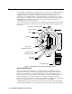
applied to the white wire of the propane detector near where the wire comes out of the nipple. Amplifier The amplifier converts the electrical output from the detector to a 4 to 20 mA signal that corresponds to the detection range and transmits the signal to a gas monitoring controller. The amplifier includes the interconnect terminal strip, span potentiometer, zero potentiometer, and test points (see Figure 1). Interconnect Terminal Strip The interconnect terminal strip is a seven-point terminal strip.
Installation This section describes procedures to mount the combustible gas transmitter in the monitoring environment and wire the transmitter to a controller. Mounting the Combustible Gas Transmitter 1. Select a mounting site that is representative of the monitoring environment. Consider the following when you select the mounting site. • Select a site where the transmitter is not likely to be bumped or disturbed.
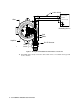
CAUTION: Mount the combustible gas transmitter with the detector facing down (see Figure 2.) Wiring the Combustible Gas Transmitter to a Controller WARNING: Always verify that the power to the controller is off before you make wiring connections. 1. Turn off power to the controller. 2. Place the controller’s power switch in the OFF position. 3. Remove the junction box cover. 4. Verify that the detector leads are wired to the amplifier’s interconnect terminal strip.
Cable Shield - (DC Ground) + 24 VDC J-Box P OWER/SIG 4 - 20 mA In (FB) Controller or Recording Device GND 24V 4/20 S ENSOR RED WHT GRN BLK Red White Amplifier IR LEL Detector Black Green Figure 3: Wiring the Combustible Gas Transmitter to a Controller 10. If shielded cable is used, connect the cable’s drain wire to an available chassis ground at the controller.
Start Up This section describes procedures to start up the combustible gas transmitter and place the transmitter into normal operation. Introducing Incoming Power 1. Complete the installation procedures described earlier in this manual. 2. Verify that the power wiring to the controller is correct and secure. Refer to the controller operator’s manual. 3. Turn on or plug in power to the controller, then place the controller’s power switch in the ON position. 4.
Maintenance This section describes maintenance procedures. It includes preventive maintenance, troubleshooting, and component replacement procedures. Preventive Maintenance This section describes a preventive maintenance schedule to ensure the optimum performance of the combustible gas transmitter. It includes daily, monthly, and biannual procedures. Daily Verify a display reading of 0 %LEL at the controller. Investigate significant changes in the display reading.
7. Use the following formula to determine the correct test points output for the test sample. Output (mV) = (calibrating sample/fullscale) X 400 + 100 For example, with a test sample of 50% LEL and a fullscale setting of 100% LEL, the correct output is 300 mV. 300 (mV) = (50/100) X 400 +100 Performing the response test 1. Screw the regulator into the calibration cylinder. 2. Turn the regulator knob counterclockwise to open the regulator. 3. Allow the gas to flow for one minute. 4.
Troubleshooting The troubleshooting guide describes symptoms, probable causes, and recommended action for problems you may encounter with the combustible gas transmitter. NOTE: This troubleshooting guide describes transmitter problems only. See the controller operator’s manual for problems you may encounter with the controller. Table 2:Troubleshooting the Combustible Gas Transmitter Condition Symptom(s) Probable Causes Recommended Action Fail Condition • Controller indicates a fail condition.
Replacing Components of the Combustible Gas Transmitter This section includes procedures to replace the IR LEL detector and amplifier. Replacing the IR LEL Detector 1. Turn off power to the controller. 2. Place the controller’s power switch in the OFF position. 3. Remove the junction box cover. 4. Disconnect the detector leads from the interconnect terminal strip. Note the position of the color-coded leads as you remove them. 5. Unscrew the detector from the junction box. 6.
4. Disconnect the detector leads from the interconnect terminal strip. 5. Disconnect the wiring that connects the combustible gas transmitter to the controller from the amplifier’s interconnect terminal strip. 6. Unscrew and remove the two screws that secure the amplifier to the junction box. The screws are at the top left and bottom right of the amplifier. 7. Remove the amplifier. 8. Place the new amplifier in the same position as the amplifier you removed in the previous step. 9.
CAUTION: Allow the detector to warm up for 5 minutes before you continue with the next step. 14. Calibrate the combustible gas transmitter as described in “Calibration” on page 13 of this manual. Calibration Frequency Although there is no particular calibration frequency that is correct for all applications, a calibration frequency of every 6 months is adequate for most infrared combustible gas transmitter applications. Unless experience in a particular application dictates otherwise, RKI Instruments, Inc.
5. Use the following formula to determine the correct test points output for the calibrating sample. Output (mV) = (calibrating sample/fullscale) X 400 + 100 For example, with a calibrating sample of 50% LEL and a fullscale setting of 100% LEL, the correct output is 300 mV. 300 (mV) = (50/100) X 400 +100 6. Place the controller into its calibration program or disable external alarms. NOTE: Calibrating the combustible transmitter may cause alarms.
normal operation. 5. Verify that the controller display reading decreases and stabilizes at 0%LEL. 6. Store the components of the calibration kit in a safe and convenient place. Parts List Table 6 lists replacement parts and accessories for the combustible gas transmitter. Table 6:Parts List Part Number Description 06-1248RK Sample tubing (3/16 in. x 5/16 in.