65-2391RK CO2 Transmitter Operator’s Manual Part Number: 71-0121RK Revision: B Released: 7/18/14 www.rkiinstruments.
WARNING Read and understand this instruction manual before operating transmitter. Improper use of the transmitter could result in bodily harm or death. Periodic calibration and maintenance of the transmitter is essential for proper operation and correct readings. Please calibrate and maintain this transmitter regularly! Frequency of calibration depends upon the type of use you have and the sensor types.
Product Warranty RKI Instruments, Inc., warrants gas alarm equipment sold by us to be free from defects in materials, workmanship, and performance for a period of one year from date of shipment from RKI Instruments, Inc. Any parts found defective within that period will be repaired or replaced, at our option, free of charge.
Table of Contents Overview . . . . . . . . . . . . . . . . . . . . . . . . . . . . . . . . . . . . . . . . . . . . . . . . . . . . . . . . . . . . . . . . . . . 1 Specifications. . . . . . . . . . . . . . . . . . . . . . . . . . . . . . . . . . . . . . . . . . . . . . . . . . . . . . . . . . . . . . . . 1 Description . . . . . . . . . . . . . . . . . . . . . . . . . . . . . . . . . . . . . . . . . . . . . . . . . . . . . . . . . . . . . . . . . . 2 IR CO2 Detector. . . . . . . . . . . . . . . . . . . . . .
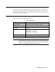
Overview This manual describes the 65-2391RK CO2 transmitter. This manual also describes how to install, start up, configure, maintain, and calibrate the transmitter when it is used with a gas monitoring controller. A parts list at the end of this manual lists replacement parts and accessories for the CO2 transmitter. Specifications Table 1 lists specifications for the CO2 transmitter.
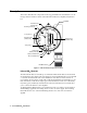
Description This section describes the components of the CO2 transmitter. The transmitter is a 4 - 20 mA type detector head. It consists of the infrared CO2 detector, amplifier, and junction box.
Table 2: CO2 Detector Color Designations Detector Color Designations 0 - 5,000 ppm black shrink tubing on white wire 0 - 5% volume green shrink tubing on white wire 0 - 50% volume green shrink tubing on red wire 0 - 100% volume red shrink tubing on green wire Amplifier The amplifier converts the electrical output from the detector to a 4 to 20 mA signal that corresponds to the detection range and transmits the signal to a gas monitoring controller.
Junction Box Use the junction box to install the CO2 transmitter at a mounting site that is remote from the controller. The junction box also protects the amplifier and wiring connections made to the amplifier. Use the two 3/4 in. conduit hubs to mount the detector to the junction box (bottom hub) and connect wiring from the amplifier to the controller (top hub). NOTE: The detector and amplifier are factory-mounted to the junction box.
If the detector is mounted to the junction box, skip to step 5. If not, continue with step 2. 2. Remove the junction box cover. 3. Guide the four wires that extend from the top of the detector through the bottom conduit hub of the junction box. 4. Screw the detector into the bottom conduit hub of the junction box. 5. At the monitoring site, use #10 screws through the junction box’s two mounting holes to secure the junction box to a vertical surface.
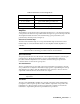
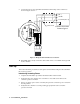
9. Connect the wires to the applicable transmitter terminal strip at the controller as shown in Figure 3 below. - (DC -) + 24 VDC 4 - 20 mA In (FB or S) TP+ POWER/SIG Cable Shield GND Controller Transmitter Terminals,Typical 24V 4-20 SENSOR RED WHT GRN BLK Black Green White Red TP- Figure 3: Wiring the CO2 Transmitter to a Controller 10. If shielded cable is used, connect the cable’s drain wire to an available chassis ground at the controller.
NOTE: When first powered up, the transmitter will enter about a one minute period when the 4-20 mA output is stabilizing and may be above the controller alarm points or well below zero momentarily. RKI controllers have a one minute warmup period when the controller does not display any gas reading or give any alarm indication. The CO2 transmitter’s 4-20 mA signal should be stable by the time the controller’s warmup period is over.
Maintenance This section describes maintenance procedures. It includes preventive maintenance, troubleshooting, and component replacement procedures. Preventive Maintenance This section describes a preventive maintenance schedule to ensure the optimum performance of the CO2 transmitter. It includes daily, monthly, and biannual procedures. Daily Verify a display reading at the controller of the background concentration of CO2. Typical background concentrations of CO2 vary from about 300 to 600 ppm (0.
test point labeled TP-. 7. Use the following formula to determine the correct test points output for the test sample. Output (mV) = (calibrating sample/fullscale) X 400 + 100 For example, with a test sample of 2.5% CO2 and a fullscale setting of 5% CO2, the correct output is 300 mV. 300 (mV) = (2.5/5) X 400 +100 Performing the response test 1. Screw the regulator into the calibration cylinder. 2. Turn the regulator knob counterclockwise to open the regulator. 3. Allow the gas to flow for one minute.
Troubleshooting The troubleshooting guide describes symptoms, probable causes, and recommended action for problems you may encounter with the CO2 transmitter. NOTE: This troubleshooting guide describes transmitter problems only. See the controller operator’s manual for problems you may encounter with the controller. Table 3:Troubleshooting the CO2 Transmitter Condition Symptom(s) Probable Causes Recommended Action Fail Condition • Controller indicates a fail condition.
Replacing Components of the CO2 Transmitter This section includes procedures to replace the IR CO2 detector and amplifier. Replacing the IR CO2 Detector 1. Turn off power to the controller. 2. Place the controller’s power switch in the OFF position. 3. Remove the junction box cover. 4. Disconnect the detector leads from the interconnect terminal strip. Note the position of the color-coded leads as you remove them. 5. Unscrew the detector from the junction box. 6.
3. Remove the junction box cover. 4. Disconnect the detector leads from the interconnect terminal strip. 5. Disconnect the wiring that connects the CO2 transmitter to the controller from the amplifier’s interconnect terminal strip. 6. Unscrew and remove the two screws that secure the amplifier to the junction box. The screws are at the top left and bottom right of the amplifier. 7. Remove the amplifier. 8.
NOTE: When first powered up, the transmitter will enter about a one minute period when the 4-20 mA output is stabilizing and may be above the controller alarm points or well below zero momentarily. RKI controllers have a one minute warmup period when the controller does not display any gas reading or give any alarm indication. The CO2 transmitter’s 4-20 mA signal should be stable by the time the controller’s warmup period is over.
the amplifier. Plug the positive lead into the test point labeled TP+; plug the negative lead into the test point labeled TP-. 5. Use the following formula to determine the correct test points output for the calibrating sample. Output (mV) = (calibrating sample/fullscale) X 400 + 100 For example, with a calibrating sample of 2.5% CO2 and a fullscale setting of 5% CO2, the correct output is 300 mV. 300 (mV) = (2.5/5) X 400 +100 6.
Returning to Normal Operation 1. Remove the voltmeter leads from the amplifier test points. 2. Unscrew the calibration cup from the detector. NOTE: For convenience, leave the regulator and calibration cup connected by the sample tubing. 3. Secure the junction box cover to the junction box. 4. When the display reading falls below the alarm setpoints, return the controller to normal operation. 5. Verify that the controller display reading decreases and stabilizes at a typical background CO2 level.
Table 7:Parts List Part Number Description 81-0073RK-01 Steel calibration cylinder, 15% CO2, 34-liter 81-0076RK-01 Zero air calibration cylinder (34-liter) 81-1050RK Regulator, 0.