65-2422RK-05 Hydrogen Sulfide Transmitter Operator’s Manual Part Number: 71-0114RK Revision: B Released: 7/18/14 www.rkiinstruments.
WARNING Read and understand this instruction manual before operating detector. Improper use of the detector could result in bodily harm or death. Periodic calibration and maintenance of the detector is essential for proper operation and correct readings. Please calibrate and maintain this detector regularly! Frequency of calibration depends upon the type of use you have and the sensor types.
Product Warranty RKI Instruments, Inc. warrants gas alarm equipment sold by us to be free from defects in materials, workmanship, and performance for a period of one year from date of shipment from RKI Instruments, Inc. Any parts found defective within that period will be repaired or replaced, at our option, free of charge.
Table of Contents Overview . . . . . . . . . . . . . . . . . . . . . . . . . . . . . . . . . . . . . . . . . . . . . . . . . . . . . . . . . . . . . . . . . . . 1 Specifications. . . . . . . . . . . . . . . . . . . . . . . . . . . . . . . . . . . . . . . . . . . . . . . . . . . . . . . . . . . . . . . . 1 Description . . . . . . . . . . . . . . . . . . . . . . . . . . . . . . . . . . . . . . . . . . . . . . . . . . . . . . . . . . . . . . . . . . 2 H2S Detector . . . . . . . . . . . . . . . . . . . . . . .
Overview This manual describes the hydrogen sulfide (H2S) transmitter. This manual also describes how to install, start up, maintain, and calibrate the transmitter. A parts list at the end of this manual lists replacement parts and accessories for the H2S transmitter. Specifications WARNING: Do not use this product in a manner not specified in this instruction manual. Table 1 lists specifications for the H2S transmitter.
Description This section describes the components of the H2S transmitter. The transmitter consists of the H2S detector, amplifier, and junction box.
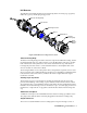
H2S Detector The H2S detector includes the detector housing body, detector housing cap, cap gasket, rubber boot, spacer, and the plug-in H2S sensor. Detector Housing Body Cap Gasket H2S Plug-in Sensor Spacer Rubber Boot Detector Housing Cap Flame Arrestor Guard Figure 2: H2S Detector Component Location Detector Housing Body The detector housing body protects the electronic components within the housing.
chemical and electrical reactions, the sensor produces an electrical output that is proportional to the detector range of the transmitter. Amplifier The amplifier converts the electrical output from the sensor to a 4 to 20 mA signal (that is proportional to the detection range) and transmits the signal to a gas monitoring controller. The amplifier includes the amplifier type selector, detector terminal strip, interconnect terminal strip, span pot, zero pot, and test points (see Figure 1).
NOTE: The H2S detector and amplifier are factory-mounted to the junction box. Use the junction box’s two mounting holes to mount the H2S transmitter to a vertical surface at the monitoring site. Use the cover on the front of the junction box to access the interior of the junction box. Installation This section describes procedures to mount the H2S transmitter in the monitoring environment and wire the transmitter to a controller. Mounting the H2S Transmitter 1.
If the H2S detector is mounted to the junction box, skip to step 5. If not, continue with step 2. NOTE: The H2S detector is normally provided with a Killark HKB junction box and an HFC lid rated explosion proof for Class I, Groups B, C, and D. This combination is shown in Figure 2 above. Any junction box with an internal volume less than or equal to 69 cubic inches and rated explosion proof for ClassI, Groups B, C, and D may be used. 2. Remove the junction box cover. 3.
CAUTION: If using shielded cable, leave the drain wire insulated and disconnected at the transmitter. You will connect the opposite end of the cable’s drain wire at the controller. 8. Secure the junction box cover to the junction box. 9. Route the cable or wires leading from the H2S transmitter through one of the conduit hubs at the controller housing. CAUTION: Do not route power and transmitter wiring through the same conduit hub.
Start Up This section describes procedures to start up the H2S transmitter and place the transmitter into normal operation. Introducing Incoming Power 1. Complete the installation procedures described earlier in this manual. 2. Verify that the power wiring to the controller is correct and secure. Refer to the controller instruction manual. 3. Turn on or plug in the incoming power at the power source end, then turn on the controller. 4. Verify that the controller is on and operating properly.
12. Unscrew the calibration cup from the detector. 13. Unscrew the regulator from the zero air calibration cylinder. For convenience, leave the sample tubing connected to the regulator and the calibration cup. 14. Store the components of the calibration kit in a safe and convenient place. 15. Remove the voltmeter leads from the test points. 16. Secure the junction box cover to the junction box. Maintenance This section describes maintenance procedures.
test point labeled TP-. 8. Use the following formula to determine the correct test points output for the test sample. Output (mV) = (calibrating sample/fullscale) X 400 + 100 For example, with a test sample of 25 PPM H2S and a fullscale setting of 100 PPM, the correct output is 200 mV. 200 (mV) = (25/100) X 400 +100 Performing the response test 1. Turn the regulator on/off knob counterclockwise to open it. The sample will begin to flow. 2.
Recommended action • Verify that the transmitter wiring is correct and secure. • Calibrate the transmitter. • If the fail condition continues, replace the H2S sensor. • If the fail condition continues, contact RKI for further instruction. Slow or No Response/Difficult or Unable to Calibrate Symptoms • The transmitter responds slowly or does not respond during the monthly response test. • Unable to accurately set the zero or response reading during the calibration procedure.
7. Carefully plug the replacement sensor into the socket pattern that is located in the top section of the detector housing. NOTE: Match the sensor’s male pins with the four female sockets as you plug the sensor into the socket. 8. Screw the bottom section of the detector housing onto the top section. 9. Turn on or plug in incoming power at the power source end. 10. Turn on the controller. CAUTION: Allow the replacement sensor to warm up for 5 minutes before you continue with the next step. 11.
11. Reconnect the detector leads to the detector terminal strip as shown in Table 3 and Figure 3. Table 3: Reconnecting the H2S Detector to the Amplifier H2S Detector Lead Amplifier Interconnect Terminal Strip Black TOXIC BK Red TOXIC RD 12. Reinstall the junction box cover. 13. Turn on or plug in incoming power at the power source end. 14. Turn on the controller. CAUTION: Allow the sensor to warm up for 5 minutes before you continue with the next step. 15.
CAUTION: Allow the replacement detector to warm up for 5 minutes before you continue with the next step. 11. Calibrate the replacement detector as described in the Calibration section of this manual. 12. Secure the junction box cover to the junction box. Calibration Frequency Although there is no particular calibration frequency that is correct for all applications, a calibration frequency of every 3 months is adequate for most H2S transmitter applications.
6. Use the following formula to determine the correct test points output for the calibrating sample. Output (mV) = (calibrating sample/fullscale) X 400 + 100 For example, with a calibrating sample of 25 PPM H2S and a fullscale setting of 100 PPM, the correct output is 200 mV. 200 (mV) = (25/100) X 400 +100 Setting the Zero Reading NOTE If you can verify that the H2S transmitter is in a fresh air environment, you do not need to apply zero air to the detector before adjusting the zero reading. 1.
Parts List Table 5 lists replacement parts and accessories for the H2S transmitter.