65-2435RK Hydrogen Compensated Carbon Monoxide Transmitter Operator’s Manual Part Number: 71-0073RK Revision: A Released: 2/20/14 RKI Instruments, Inc. www.rkiinstruments.
Product Warranty RKI Instruments, Inc., warrants gas alarm equipment sold by us to be free from defects in materials, workmanship, and performance for a period of one year from date of shipment from RKI Instruments, Inc. Any parts found defective within that period will be repaired or replaced, at our option, free of charge.
Table of Contents Overview . . . . . . . . . . . . . . . . . . . . . . . . . . . . . . . . . . . . . . . . . . . . . . . . . . . . . . . . . . . . . . . . . . . . 4 Specifications . . . . . . . . . . . . . . . . . . . . . . . . . . . . . . . . . . . . . . . . . . . . . . . . . . . . . . . . . . . . . . . . . 4 Description. . . . . . . . . . . . . . . . . . . . . . . . . . . . . . . . . . . . . . . . . . . . . . . . . . . . . . . . . . . . . . . . . . . 5 CO Detector . . . . . . . . . . . . . . . . . . . . .
Overview This manual describes the hydrogen compensated carbon monoxide (CO) transmitter. This manual also describes how to install, start up, maintain, and calibrate the transmitter. A parts list at the end of this manual lists replacement parts and accessories for the CO transmitter. Specifications Table 1 lists specifications for the CO transmitter.
Description This section describes the components of the CO transmitter. The transmitter consists of the CO detector, amplifier, and junction box.
Charcoal Filter The disc-shaped charcoal filter is secured to face of the CO sensor with a rubber boot. The charcoal filter prevents interference gases (hydrogen sulfide [H2S] and certain hydrocarbons) from producing false CO readings. Amplifier The amplifier converts the electrical output from the sensor to a 4 to 20 mA signal (that is proportional to the detection range) and transmits the signal to a gas monitoring controller.
monitoring site. Use the cover on the front of the junction box to access the interior of the junction box. Installation This section describes procedures to mount the CO transmitter in the monitoring environment and wire the transmitter to a controller. Mounting the CO Transmitter 1. Select a mounting site that is representative of the monitoring environment. Consider the following when you select the mounting site. • Select a site where the transmitter is not likely to be bumped or disturbed.
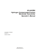
Wiring the CO Transmitter to a Controller WARNING: Always verify that the power source is OFF before you make wiring connections. 1. Turn off the controller. 2. Turn off or unplug incoming power at the power source end. 3. Remove the junction box cover. 4. Verify that the detector leads are wired to the amplifier’s terminal strip. If necessary, connect the detector leads to the terminal strip as shown in Figure 3. 5.
. Connect the wires to the to the applicable controller transmitter terminal strip as shown in Figure 3. CO Amplifier TP+ TP FB 24V BLK NULL 4 - 20 mA In (FB) GRN 4-20mA Transmitter 57-1252RK SPAN BRN WHT ZERO +24 VDC (19 - 30 VDC) RED Controller or Recording Device RED WHT BRN GRN BLK CO Detector/ H2 Compensated Factory Wired Figure 3: Wiring the CO Transmitter to a Controller 10. Connect the cable’s drain to an available chassis ground at the controller.
Start Up This section describes procedures to start up the CO transmitter and place the transmitter into normal operation. Introducing Incoming Power 1. Complete the installation procedures described earlier in this manual. 2. Verify that the power wiring to the controller is correct and secure. Refer to the controller instruction manual. 3. Turn on or plug in the incoming power at the power source end, then turn on the controller. 4. Verify that the controller is on and operating properly.
Maintenance This section describes maintenance procedures. It includes preventive maintenance, troubleshooting, and component replacement procedures. Preventive Maintenance This section describes a preventive maintenance schedule to ensure the optimum performance of the CO transmitter. It includes daily, monthly, and quarterly procedures. Daily 1. Verify a display reading of 0 PPM CO at the controller. Investigate significant changes in the display reading.
Performing the response test 1. Screw the regulator into the calibration cylinder. The sample will begin to flow. 2. Allow the gas to flow for two minutes, then verify that the reading is within ± 10% of the response reading you determined earlier. NOTE: If the reading is not within ± 10% of the correct response reading, calibrate the transmitter as described in the Calibration section of this manual. 3. Unscrew the regulator from the calibration cylinder. 4.
NOTE: Under “normal” circumstances, the transmitter requires calibration once every three months. Some applications may require a more frequent calibration schedule. Probable causes • The calibration cylinder is low, out-dated, or defective. • The transmitter is malfunctioning. Recommended action 1. Verify that the calibration cylinder contains an adequate supply of a fresh test sample. 2. If the calibration/response difficulties continue, replace the CO sensor as described later in this section.
CAUTION: The null potentiometer must be set whenever a sensor is changed or the hydrogen compensation may not work properly. 15. Calibrate the replacement sensor as described in the Calibration section of this manual. Replacing the Charcoal Filter 1. Turn off the controller. 2. Turn off or unplug incoming power at the power source end. 3. Unscrew the bottom section of the CO detector housing from the top section. NOTE: Be sure the two cap gaskets remain seated and that they don’t fall out. 4.
9. Reconnect the wiring from the controller to the interconnect terminal strip as shown in Table 2 and Figure 3, Wiring the CO Transmitter to a Controller. Table 2: Reconnecting the CO Amplifier to a Controller Amplifier Terminal Strip Controller Transmitter Terminal Strip (typical) FB 4 -20 (FB) 24V + V (19 - 30 VDC) 10. Reconnect the detector leads to the detector terminal strip as shown in Table 3 and Figure 3, Wiring the CO Transmitter to a Controller.
7. Connect the detector leads to the detector terminal strip as shown in Table 4 and Figure 3, Wiring the CO Transmitter to a Controller. Table 4: Connecting the Replacement CO Detector to the Amplifier CO Detector Lead Amplifier Interconnect Terminal Strip Black BLK Green GRN Brown BRN White WHT Red RED 8. Reinstall the junction box cover. 9. Turn on or plug in incoming power at the power source end. 10. Turn on the controller.
Setting the Null Potentiometer When an old sensor is replaced, the null potentiometer must be adjusted so that the CO transmitter’s hydrogen compensation will work properly with the new sensor. The procedure basically involves applying hydrogen to the transmitter and using the null potentiometer to cancel out the hydrogen response. This adjustment is made only once after the sensor is replaced and does not need to be made again until the sensor is replaced again.
2. Allow the gas to flow for two minutes, then verify a reading of 100 mV (± 2mV). If necessary, use the zero potentiometer on the amplifier to adjust the reading to 100 mV (± 2mV). 3. Unscrew the regulator from the zero air calibration cylinder. Returning to Normal Operation 1. Remove the voltmeter leads from the amplifier test points. 2. Unscrew the calibration cup from the detector. NOTE: For convenience, leave the components of the calibration kit connected by the sample tubing. 3.
Calibration This section describes how to calibrate the CO transmitter. It includes procedures to prepare for calibration, set the zero reading, set the response reading, and return to normal operation. It describes calibration using a fixed flow regulator which has no on/off knob and allows sample to flow as soon as it is screwed into a cylinder. RKI Instruments, Inc. recommends using a 0.5 LPM (liters per minute) fixed flow regulator. CAUTION: Do not adjust the null potentiometer during calibration.
2. Allow the gas to flow for two minutes, then verify that the reading matches the response reading (± 2mV) you determined earlier. If necessary, use the span potentiometer on the amplifier to adjust the reading to match the correct response reading. 3. Unscrew the regulator from the calibration cylinder. Returning to Normal Operation 1. Remove the voltmeter leads from the amplifier test points. 2. Unscrew the calibration cup from the detector.
Parts List Table 5 lists replacement parts and accessories for the CO transmitter.