65-2437RK-05 Carbon Monoxide Detector Operator’s Manual Part Number: 71-0190RK Revision: 0 Released: 5/17/11 RKI Instruments, Inc. www.rkiinstruments.
WARNING Read and understand this instruction manual before operating instrument. Improper use of the detector could result in bodily harm or death. Periodic calibration and maintenance of the detector is essential for proper operation and correct readings. Please calibrate and maintain this detector regularly! Frequency of calibration depends upon the type of use you have and the sensor types.
Product Warranty RKI Instruments, Inc. warrants gas alarm equipment sold by us to be free from defects in materials, workmanship, and performance for a period of one year from date of shipment from RKI Instruments, Inc. Any parts found defective within that period will be repaired or replaced, at our option, free of charge.
Table of Contents Overview . . . . . . . . . . . . . . . . . . . . . . . . . . . . . . . . . . . . . . . . . . . . . . . . . . . . . . . . . . . . . . . . . . . 1 Specifications. . . . . . . . . . . . . . . . . . . . . . . . . . . . . . . . . . . . . . . . . . . . . . . . . . . . . . . . . . . . . . . . 1 Description . . . . . . . . . . . . . . . . . . . . . . . . . . . . . . . . . . . . . . . . . . . . . . . . . . . . . . . . . . . . . . . . . . 2 CO Detector . . . . . . . . . . . . . . . . . . . . . . . .
Overview This manual describes the 65-2437RK-05 carbon monoxide (CO) detector. This manual also describes how to install, start up, maintain, and calibrate the detector when it is used with a gas monitoring controller. A parts list at the end of this manual lists replacement parts and accessories for the CO detector. Specifications WARNING: Do not use this product in a manner not specified in this instruction manual. Table 1 lists specifications for the CO detector.
Description This section describes the components of the 65-2437RK-05 CO detector. The 65-2437RK-05 consists of the 65-2433RK-05 CO detector and junction box.
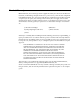
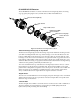
65-2433RK-05 CO Detector The 65-2433RK-05 CO detector consists of the detector housing body, detector housing cap, cap gasket, the plug-in sensor, and the charcoal filter with rubber boot. Detector Housing Body Cap Gasket Plug-In CO Sensor Rubber Boot With Charcoal Filter Detector Housing Cap Flame Arrestor Guard Figure 2: CO Detector Component Location Detector Housing, Housing Cap, & Cap Gasket The detector housing body protects the sensing components within the housing.
Junction Box The junction box allows you to install the detector at a mounting site that is remote from a controller, and it protects the detector wiring connections. Two conduit hubs allow you to mount the detector to the junction box and connect the wiring from the detector to a controller.
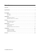
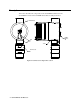
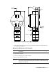
3.10 3/4 NPT Female .75 .38 3.65 8.25 MAX Rubber Spacers 3X J-Box C O Detector 1-1/2 - 20 Thread for Calibration Cup Figure 3: Outline & Mounting Dimensions 2. At the monitoring site you select, hang or mount the junction box with the detector facing down (see Figure 3). Wiring the CO Detector to a Controller WARNING: Always verify that the power source is OFF before you make wiring connections. 1. Turn off the controller. 2. Turn off or unplug power to the controller. 3.
4. Guide a two-conductor, shielded cable or two wires in conduit through an unused conduit hub of the junction box. Use appropriate conduit fittings and construction technique for the environmental and hazardous location rating of the junction box. The junction box is rated NEMA 4X and Class 1, Division 1, Groups B, C, D. 5. Connect the two wires to the detector using the 2 point terminal block. CAUTION: If using shielded cable, leave the drain wire insulated and disconnected at the detector.
9. If using shielded cable, connect the cable’s drain wire to an available chassis ground at the controller. RKI controllers typically have a ground stud that is a convenient grounding location. 10. Reinstall the junction box cover. Start Up This section describes procedures to start up the CO detector and place the detector into normal operation. Introducing Incoming Power 1. Complete the installation procedures described earlier in this manual. 2.
Maintenance This section describes maintenance procedures. It includes preventive maintenance, troubleshooting, and component replacement procedures. Preventive Maintenance This section describes a preventive maintenance schedule to ensure the optimum performance of the CO detector. It includes daily, monthly, and quarterly procedures. Daily Verify a display reading of 0 PPM CO at the controller. Investigate significant changes in the display reading.
6. When the controller display reading falls below the alarm setpoints, return the controller to normal operation. 7. Store the components of the calibration kit in a safe place. Quarterly Calibrate the CO detector as described in the Calibration section of this manual. Troubleshooting The troubleshooting guide describes symptoms, probable causes, and recommended action for problems you may encounter with the CO detector. NOTE: This troubleshooting guide describes detector problems only.
Replacing Components of the CO Detector This section includes a procedure to replace the CO sensor, the charcoal filter, and the entire detector assembly. In most cases, it is not necessary to replace the entire detector assembly. Replacing the Plug-In CO Sensor CAUTION: The sensor contains electrolyte which is a dilute acid. Do not disassemble the sensor when replacing it with a new one. If sensor electrolyte comes in contact with your skin, wash affected area thoroughly with soap and water. 1.
11. Turn on or plug in power to the controller. 12. Turn on the controller and place into normal operation. Replacing the CO Detector NOTE: In most cases, it is only necessary to replace the CO sensor. 1. Turn off the controller. 2. Turn off or unplug power to the controller. 3. Remove the junction box cover. 4. Disconnect the detector leads from the terminal block in the junction box. Note the position of the color-coded leads as you remove them. 5. Unscrew the detector from the junction box hub.
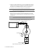
Calibration This section describes how to calibrate the CO detector. It includes procedures to prepare for calibration, set the zero reading, set the response reading, and return to normal operation. It describes calibration using a calibration kit that includes a calibration cup, calibration gas, sample tubing, and a fixed flow regulator with an on/off knob. RKI Instruments, Inc. recommends using a 0.5 LPM (liters per minute) fixed flow regulator.
3. When the directions call for exposing the detector to gas, turn the regulator’s on/off knob counterclockwise to open it. 4. Allow gas to flow for 2 minutes. 5. Set the response reading according to the controller operator’s manual. 6. After setting the response reading, turn the regulator’s on/off knob clockwise to close it. 7. Unscrew the regulator from the cylinder. 8. Remove the calibration cup from the detector.
Parts List Table 5 lists replacement parts and accessories for the CO detector.