65-2442RK PPM Hydrogen Transmitter Operator’s Manual Part Number: 71-0139RK Revision: 0 Released: 2/16/11 RKI Instruments, Inc. www.rkiinstruments.
WARNING Read and understand this instruction manual before operating detector. Improper use of the detector could result in bodily harm or death. Periodic calibration and maintenance of the detector is essential for proper operation and correct readings. Please calibrate and maintain this detector regularly! Frequency of calibration depends upon the type of use you have and the sensor types.
Product Warranty RKI Instruments, Inc. warrants gas alarm equipment sold by us to be free from defects in materials, workmanship, and performance for a period of one year* from the date of shipment from RKI Instruments, Inc. Any parts found defective within that period will be repaired or replaced, at our option, free of charge. Parts must be returned to RKI Instruments, Inc. for repair or replacement.
Table of Contents Overview . . . . . . . . . . . . . . . . . . . . . . . . . . . . . . . . . . . . . . . . . . . . . . . . . . . . . . . . . . . . . . . . . . . 1 Specifications. . . . . . . . . . . . . . . . . . . . . . . . . . . . . . . . . . . . . . . . . . . . . . . . . . . . . . . . . . . . . . . . 1 Description . . . . . . . . . . . . . . . . . . . . . . . . . . . . . . . . . . . . . . . . . . . . . . . . . . . . . . . . . . . . . . . . . . 2 PPM Hydrogen Detector . . . . . . . . . . . . . . . . . . .
Overview This manual describes the 65-2442RK ppm hydrogen transmitter. This manual also describes how to install, start up, configure, maintain, and calibrate the transmitter when it is used with a gas monitoring controller. A parts list at the end of this manual lists replacement parts and accessories for the transmitter. Specifications Table 1 lists specifications for the ppm hydrogen transmitter.
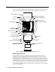
Description This section describes the ppm hydrogen transmitter’s components. It is a 4 to 20 mA type detector head. It consists of the ppm hydrogen detector, amplifier, and junction box.
The detector has a built in molecular sieve that only allows hydrogen to diffuse into the detector. The output of the detector is non-linear and is linearized by the amplifier (see below). Amplifier The amplifier converts the non-linear electrical output from the detector to a linear 4 to 20 mA signal that corresponds to the detection range and transmits the signal to a gas monitoring controller.
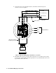
Test Points The test points are in the lower left corner of the amplifier on either side of the gas select jumper strip (see Figure 1). The test points produce a 100 to 500 mV output that corresponds to the transmitter’s 4 to 20 mA output. Use the test points and a voltmeter to measure the amplifier’s output during the start-up and calibration procedures. The black test point on the left is the negative (-) test point and the red test point on the right is the positive (+) test point.
1. 2. Select a mounting site that is representative of the monitoring environment. Consider the following when you select the mounting site. • Select a site where the transmitter is not likely to be bumped or disturbed. Make sure there is sufficient room to perform start-up, maintenance, and calibration procedures. • Select a site where the target gas is likely to be found first.
11. Connect the wires to the applicable detector/transmitter terminal strip at the controller as shown in Figure 3. + 24 VDC 4 - 20 mA In (S) - (DC Ground) Controller S R B DET ECT OR W 1 Gas Select 2 1-2 Hex 3 3-4 H2 4 PWR / SIG Cable Shield Red Black Detector W ires White Gas Select Jumper, In Hydrogen Position Figure 3: Wiring the PPM Hydrogen Transmitter to a Controller 12. If shielded cable is used, connect the cable’s drain wire to an available chassis (earth) ground at the controller.
Start Up This section describes procedures to start up the ppm hydrogen transmitter and place the transmitter into normal operation. Introducing Incoming Power 1. Complete the installation procedures described earlier in this manual. 2. Verify that the power wiring to the controller is correct and secure. Refer to the controller operator’s manual.
4. Plug the voltmeter leads into the test points on the amplifier. Plug the positive lead into the red + test point; plug the negative lead into the black - test point. 5. Verify a voltmeter reading of 100 mV (±2 mV). 6. If necessary, use a small flat-blade screwdriver to adjust the zero pot until the voltmeter reading is 100 mV (±2 mV). 7. Remove the voltmeter leads from the test points. 8. Secure the junction box cover to the junction box.
6. Remove the junction box cover, then plug the voltmeter leads into the test points on the amplifier. Plug the positive lead into the red + test point; plug the negative lead into the black test point. 7. Use the following formula to determine the correct test points output for the test sample. Output (mV) = (calibrating sample/fullscale) X 400 + 100 For example, with a test sample of 1,000 ppm hydrogen and a fullscale setting of 2,000 ppm hydrogen, the correct output is 300 mV.
Troubleshooting The troubleshooting guide describes symptoms, probable causes, and recommended action for problems you may encounter with the ppm hydrogen transmitter. NOTE: This troubleshooting guide describes transmitter problems only. See the controller operator’s manual for problems you may encounter with the controller. Table 2:Troubleshooting the ppm Hydrogen Transmitter Condition Symptom(s) Probable Causes Recommended Action Fail Condition • Controller indicates a fail condition.
hub. 8. Connect the detector leads to the detector terminal strip as shown in Table 3 below and Figure 3 on page 6 of this manual. Table 3:Reconnecting the PPM Detector to the Amplifier 9. Detector Lead Amplifier Interconnect Terminal Strip Red DETECTOR “R” White DETECTOR “W” Black DETECTOR “B” Re-install the detector terminal strip into its socket.
amplifier to the junction box. 6. Remove the old amplifier. 7. Install the detector and controller terminal strips into their sockets on the new amplifier as shown in Figure 3 on page 6 of this manual. If controller leads or detector leads were removed during this procedure, refer to Tables 4 and 5 below.
15. Allow the replacement detector to burn-in for at least 5 days before you continue with the next step. A burn-in period of 7 days is recommended. 16. After the burn-in period, set the load voltage as described in “Setting the Detector Load Voltage” on page 13. 17. After setting the load voltage, calibrate the transmitter as described in “Calibration” on page 15 of this manual.
9. Measure the voltage between the B terminal on the detector terminal strip and the (negative) terminal on the controller terminal strip as shown below in Figure 4. PWR / SIG S R B W 1 Gas Select 2 1-2 Hex 3 3-4 H2 4 Digital Voltmeter DETECTOR SPAN ZERO Controller Terminal Strip Measure Load Voltage Between B and - + Detector Terminal Strip NOTE: Detector and Controller Wires Not Shown Figure 4: Load Voltage Measurement 10. Adjust the load voltage adjust pot until the load voltage is 5.
Calibration This section describes how to calibrate the ppm hydrogen transmitter. It includes procedures to prepare for calibration, set the zero reading, set the response reading, and return to normal operation. WARNING: The controller is not an active gas monitoring device during the calibration procedure. NOTE: The following procedure assumes the use of a calibration kit which includes a calibration gas cylinder, a 0.
NOTE: Calibrating the ppm hydrogen transmitter may cause alarms. Be sure to put the controller into its calibration program or disable external alarms before continuing. Setting the Zero Reading NOTE: If you can verify that the ppm hydrogen transmitter is in a fresh air environment, you do not need to apply zero air to the detector before adjusting the zero reading. 1. Screw the regulator into the zero air calibration cylinder. 2. Turn the regulator knob counterclockwise to open the regulator. 3.
Parts List Table 6 lists replacement parts and accessories for the ppm hydrogen transmitter.