65-2451RK Hydrogen Transmitter Operator’s Manual Part Number: 71-0133RK Revision: C Released: 5/17/11 RKI Instruments, Inc. www.rkiinstruments.
WARNING Read and understand this instruction manual before operating transmitter. Improper use of the transmitter could result in bodily harm or death. Periodic calibration and maintenance of the transmitter is essential for proper operation and correct readings. Please calibrate and maintain this transmitter regularly! Frequency of calibration depends upon the type of use you have and the sensor types.
Product Warranty RKI Instruments, Inc., warrants gas alarm equipment sold by us to be free from defects in materials, workmanship, and performance for a period of one year from date of shipment from RKI Instruments, Inc. Any parts found defective within that period will be repaired or replaced, at our option, free of charge.
Table of Contents Overview . . . . . . . . . . . . . . . . . . . . . . . . . . . . . . . . . . . . . . . . . . . . . . . . . . . . . . . . . . . . . . . . . . . 1 Specifications. . . . . . . . . . . . . . . . . . . . . . . . . . . . . . . . . . . . . . . . . . . . . . . . . . . . . . . . . . . . . . . . 1 Description . . . . . . . . . . . . . . . . . . . . . . . . . . . . . . . . . . . . . . . . . . . . . . . . . . . . . . . . . . . . . . . . . . 2 Hydrogen Detector . . . . . . . . . . . . . . . . . . . . .
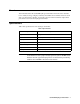
Overview This manual describes the 65-2451RK hydrogen transmitter. This manual also describes how to install, start up, configure, maintain, and calibrate the transmitter when it is used with a gas monitoring controller. A parts list at the end of this manual lists replacement parts and accessories for the hydrogen transmitter. Specifications Table 1 lists specifications for the hydrogen transmitter.
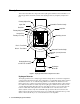
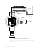
Description This section describes the components of the hydrogen transmitter. The transmitter is a 4 20 mA type detector head. It consists of the hydrogen detector, amplifier, and junction box.
Amplifier The amplifier converts the electrical output from the detector to a 4 to 20 mA signal that corresponds to the detection range and transmits the signal to a gas monitoring controller. A foam gasket that orients the amplifier and keeps it from rotating is installed on the bottom of the amplifier. A label on the amplifier indicates the detector drive current. This drive current is factory set and is dictated by the combustible gas to which the detector is calibrated. Consult RKI Instruments, Inc.
controller. Use the cover on the front of the junction box to access the interior of the junction box. The detector and amplifier are factory installed in the junction box. Three spacers installed on the back of the junction box control the distance of the junction box from a mounting surface and ensure that there is enough room to install a calibration cup on the detector during calibration.
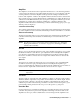
2. At the monitoring site you select, hang or mount the junction box with the detector facing down (see Figure 2). Wiring the Hydrogen Transmitter to a Controller WARNING: Always verify that the power to the controller is off before you make wiring connections. 1. Turn off power to the controller. 2. Place the controller’s power switch in the OFF position. 3. Remove the junction box cover. 4. The detector leads are factory wired.
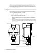
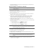
+ 24 VDC 4 - 20 mA In (S) - (DC Ground) Cable Shield Controller or Recording Device S PWR / SIG Amplifier R W G LEL B Black Green W hite Red Detector Wires Figure 3: Wiring the Hydrogen Transmitter to a Controller 12. If shielded cable is used, connect the cable’s drain wire to an available chassis (earth) ground at the controller.
Start Up This section describes procedures to start up the hydrogen transmitter and place the transmitter into normal operation. Introducing Incoming Power 1. Complete the installation procedures described earlier in this manual. 2. Verify that the power wiring to the controller is correct and secure. Refer to the controller operator’s manual. 3. Turn on power to the controller. 4. Turn on the controller. 5. Verify that the controller is on and operating properly.
Maintenance This section describes maintenance procedures. It includes preventive maintenance, troubleshooting, and component replacement procedures. Preventive Maintenance This section describes a preventive maintenance schedule to ensure the optimum performance of the hydrogen transmitter. It includes daily, monthly, and quarterly procedures. Daily Verify a display reading of 0 %LEL at the controller. Investigate significant changes in the display reading.
7. Use the following formula to determine the correct test points output for the test sample. Output (mV) = (calibrating sample/fullscale) X 400 + 100 For example, with a test sample of 50 %LEL hydrogen and a fullscale setting of 100 %LEL, the correct output is 300 mV. 300 (mV) = (50/100) X 400 +100 Performing the response test 1. Screw the regulator into the calibration cylinder. 2. Turn the regulator knob counterclockwise to open the regulator. 3. Allow the gas to flow for one minute. 4.
Table 2:Troubleshooting the Hydrogen Transmitter Condition Symptom(s) Probable Causes Recommended Action Fail Condition • Controller indicates a fail condition. • The transmitter wiring is disconnected or misconnected. • The transmitter’s zero reading is low enough to cause a fail condition. • The transmitter is malfunctioning. 1. Verify that the transmitter wiring is correct and secure. 2. Calibrate the transmitter. 3. If the fail condition continues, replace the detector. 4.
8. Connect the detector leads to the detector terminal strip as shown in Table 3 below and Figure 3 on page 6 of this manual. Table 3:Reconnecting the Hydrogen Detector to the Amplifier 9. Detector Lead Detector Terminal Strip Red LEL “R” White LEL “W” Green LEL “G” Black LEL “B” Turn on power to the controller. 10. Turn on the controller and place it into normal operation. CAUTION: Allow the replacement detector to warm up for 5 minutes before you continue with the next step. 11.
Table 5:Reconnecting the LEL Detector to the Amplifier Amplifier Detector Terminal Strip Detector Lead DETECTOR “R” RED DETECTOR “W” WHT DETECTOR “G” GREEN DETECTOR “B” BLK NOTE: When a transmitter is first powered up with a new amplifier, the initial output may be either high or below zero depending on the setting of the zero pot. Be sure to make arrangements so that this does not cause unwanted alarms. 9. Turn on power to the controller. 10.
Calibration This section describes how to calibrate the hydrogen transmitter. It includes procedures to prepare for calibration, set the zero reading, set the response reading, and return to normal operation. WARNING: The controller is not an active gas monitoring device during the calibration procedure. NOTE: The following procedure assumes the use of a calibration kit which includes a calibration gas cylinder, a 0.
5. Unscrew the regulator from the zero air calibration cylinder. Leave the sample tubing connected to the regulator and the calibration cup. Setting the Response Reading 1. Screw the regulator into the calibration cylinder. Verify that the calibration gas is representative of the transmitter’s target gas. 2. Turn the regulator knob counterclockwise to open the regulator. 3.
Parts List Table 6 lists replacement parts and accessories for the hydrogen transmitter. Table 6:Parts List Part Number Description 06-1248RK Sample tubing (3/16 in. x 5/16 in.; specify length when ordering) 18-0001RK Reducer, 3/4 in. NPT x 1/2 in.